| DTC Code | DTC Name |
|---|---|
| Starter Signal Circuit |
DESCRIPTION
w/o Stop and Start System
While the engine is being cranked, the starter signal is also sent to terminal STA of the ECM. The starter signal mainly performs engine control when the engine is started.
w/ Stop and Start System
While the engine is being cranked, the ECM detects the starter drive signal (STA2 signal) from the engine stop and start ECU as the starter operation signal (STA signal) to perform engine control when the engine is started.
CAUTION / NOTICE / HINT
-
Inspect the fuses for circuits related to this system before performing the following procedure.
-
After replacing the ECM, the new ECM needs registration (Click here ) and initialization (Click here).
-
Read Starter Count before replacing the engine stop and start ECU, perform the replacement procedure, and then write Starter Count to the newly installed engine stop and start ECU.
-
When replacing the engine stop and start ECU or the air conditioning amplifier assembly, initialize and learn the engine stop and start ECU air conditioning information.
-
When replacing the engine stop and start ECU or airbag ECU assembly (G sensor), initialize and learn the engine stop and start ECU G sensor zero point learned information.
w/o Stop and Start System
This procedure is based on the premise that the engine can crank normally. If the engine cannot crank normally, proceed to the problem symptoms table.
PROCEDURE
- Click here
CHECK IF VEHICLE IS EQUIPPED WITH STOP AND START SYSTEM
-
Confirm the vehicle specifications.
Result Result w/ Stop and Start System w/o Stop and Start System
- w/o Stop and Start SystemClick here
- w/ Stop and Start SystemClick here
-
- Click here
READ VALUE USING GTS (STARTER SIGNAL)
-
Connect the GTS to DLC3.
-
Turn the ignition switch to ON.
-
Turn the GTS on.
-
Enter the following menus: Powertrain / Engine / Data List / Primary / Starter Signal.
- Powertrain > Engine > Data List
Tester Display Starter Signal -
-
-
-
- Powertrain > Engine > Data List
-
Check the value displayed on the GTS when the ignition switch is turned to the ON and START positions.
OK Switch Condition Starter Signal ON OFF START ON Result Proceed to OK NG
- OK
PROCEED TO NEXT SUSPECTED AREA SHOWN IN PROBLEM SYMPTOMS TABLEClick here
- NGClick here
-
- Click here
CHECK HARNESS AND CONNECTOR (ECM - CLUTCH START SWITCH ASSEMBLY OR PARK/NEUTRAL POSITION SWITCH ASSEMBLY)
Tip:
-
*1: for Manual Transmission
-
*2: for Automatic Transmission
-
Disconnect the ECM connector.
-
Disconnect the clutch start switch assembly connector.*1
-
Disconnect the park/neutral position switch assembly connector.*2
-
Measure the resistance according to the value(s) in the table below.
Standard Resistance Tester Connection Condition Specified Condition G85-22 (STA) - B2-1*1 Always Below 1 Ω G85-22 (STA) - C24-5*2 Always Below 1 Ω G85-22 (STA) or B2-1*1 - Body ground and other terminals Always 10 kΩ or higher G85-22 (STA) or C24-5*2 - Body ground and other terminals Always 10 kΩ or higher Result Proceed to OK NG
- OK
PROCEED TO NEXT SUSPECTED AREA SHOWN IN PROBLEM SYMPTOMS TABLEClick here
- NG
REPAIR OR REPLACE HARNESS OR CONNECTOR
-
- Click here
CHECK WHETHER ENGINE CAN BE CRANKED
-
Check if the engine can be cranked.
Result Result Proceed to Engine cannot be cranked A Engine can be cranked B
-
- Click here
READ VALUE USING GTS (STARTER SIGNAL)
-
Connect the GTS to the DLC3.
-
Turn the ignition switch to ON.
-
Turn the GTS on.
-
Enter the following menus: Powertrain / Engine / Data List / Primary / Starter Signal.
- Powertrain > Engine > Data List
Tester Display Starter Signal -
-
-
-
- Powertrain > Engine > Data List
-
Check the value displayed on the GTS when the ignition switch is ON and the engine stars.
OK Switch Condition Starter Signal ON OFF START ON Result Proceed to OK NG
- OKClick here
- NG
GO TO STOP AND START SYSTEM (STARTER SIGNAL CIRCUIT)Click here
-
- Click here
INSPECT ST NO. 2 RELAY
-
Inspect the ST NO. 2 relay.
Result Proceed to OK NG
- OKClick here
- NG
REPLACE ST NO. 2 RELAY
-
- Click here
INSPECT ST NO. 1 RELAY
-
Inspect the ST NO. 1 relay.
Result Proceed to OK NG
- OKClick here
- NG
REPLACE ST NO. 1 RELAY
-
- Click here
INSPECT STARTER ASSEMBLY
-
Inspect the starter assembly.
Result Proceed to OK NG
- OKClick here
- NG
REPLACE STARTER ASSEMBLYClick here
-
- Click here
CHECK HARNESS AND CONNECTOR (ST NO. 2 RELAY - STARTER ASSEMBLY)
-
Remove the ST NO. 2 relay from the engine room relay block and junction block assembly.
-
Disconnect the starter assembly connector.
-
Measure the resistance according to the value(s) in the table below.
Standard Resistance Tester Connection Condition Specified Condition ST NO. 2 relay terminal 3 - C141-2 (SL2) Always Below 1 Ω ST NO. 2 relay terminal 3 - C140-1 (ST) Always Below 1 Ω ST NO. 2 relay terminal 3 or C141-2 (SL2) - Body ground and other terminals Always 10 kΩ or higher ST NO. 2 relay terminal 3 or C140-1 (ST) - Body ground and other terminals Always 10 kΩ or higher Result Proceed to OK NG
- OKClick here
- NG
REPAIR OR REPLACE HARNESS OR CONNECTOR
-
- Click here
CHECK HARNESS AND CONNECTOR (ST NO. 2 RELAY - ECM)
-
Remove the ST NO. 2 relay from the engine room relay block and junction block assembly.
-
Disconnect the ECM connector.
-
Disconnect the engine stop and start ECM connector.
-
Measure the resistance according to the value(s) in the table below.
Standard Resistance Tester Connection Condition Specified Condition ST NO. 2 relay terminal 2 - G85-22 (STA) Always Below 1 Ω Result Proceed to OK NG
- OKClick here
- NG
REPAIR OR REPLACE HARNESS OR CONNECTOR
-
- Click here
CHECK HARNESS AND CONNECTOR (ST NO. 2 RELAY - BODY GROUND)
-
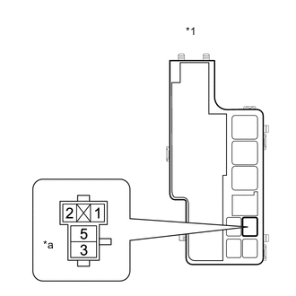
*1 Engine Room Relay Block and Junction Block Assembly *a ST NO. 2 Relay Terminal Remove the ST NO. 2 relay from the engine room relay block and junction block assembly.
-
Measure the resistance according to the value(s) in the table below.
Standard Resistance Tester Connection Condition Specified Condition ST NO. 2 relay terminal 1 - Body ground Always Below 1 Ω Result Proceed to OK NG
- OKClick here
- NG
REPAIR OR REPLACE HARNESS OR CONNECTOR
-
- Click here
CHECK HARNESS AND CONNECTOR (BATTERY - ST NO. 2 RELAY)
-
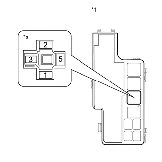
*1 Engine Room Relay Block and Junction Block Assembly *a ST NO. 2 Relay Terminal Remove the ST NO. 2 relay from the engine room relay block and junction block assembly.
-
Measure the voltage according to the value(s) in the table below.
Standard Voltage Tester Connection Condition Specified Condition ST NO. 2 relay terminal 5 - Body ground Always 11 to 14 V Result Proceed to OK NG
- OKClick here
- NG
REPAIR OR REPLACE HARNESS OR CONNECTOR
-
- Click here
CHECK HARNESS AND CONNECTOR (BATTERY - ST NO. 1 RELAY)
-
*1 Engine Room Relay Block and Junction Block Assembly *a ST NO. 1 Relay Terminal Remove the ST NO. 1 relay from the engine room relay block and junction block assembly.
-
Measure the voltage according to the value(s) in the table below.
Standard Voltage Tester Connection Condition Specified Condition ST NO. 1 relay terminal 5 - Body ground Always 11 to 14 V Result Proceed to OK NG
- OKClick here
- NG
REPAIR OR REPLACE HARNESS OR CONNECTOR
-
- Click here
CHECK HARNESS AND CONNECTOR (ST NO. 1 RELAY - STARTER ASSEMBLY)
-
Remove the ST NO. 1 relay from the engine room relay block and junction block assembly.
-
Disconnect the starter assembly connector.
-
Measure the resistance according to the value(s) in the table below.
Standard Resistance Tester Connection Condition Specified Condition ST NO. 1 relay terminal 3 - C141-1 (SL1) Always Below 1 Ω ST NO. 1 relay terminal 3 or C141-1 (SL1) - Body ground and other terminals Always 10 kΩ or higher Result Proceed to OK NG
- OKClick here
- NG
REPAIR OR REPLACE HARNESS OR CONNECTOR
-
- Click here
CHECK HARNESS AND CONNECTOR (ST NO. 1 RELAY - BODY GROUND)
-
*1 Engine Room Relay Block and Junction Block Assembly *a ST NO. 1 Relay Terminal Remove the ST NO. 1 relay from the engine room relay block and junction block assembly.
-
Measure the resistance according to the value(s) in the table below.
Standard Resistance Tester Connection Condition Specified Condition ST NO. 1 relay terminal 1 - Body ground Always Below 1 Ω Result Proceed to OK NG
- OK
REPAIR OR REPLACE HARNESS OR CONNECTOR (BATTERY - STARTER ASSEMBLY)
- NG
REPAIR OR REPLACE HARNESS OR CONNECTOR
-
- Click here
READ VALUE USING GTS (STARTER SIGNAL)
-
Connect the GTS to the DLC3.
-
Turn the ignition switch to ON.
-
Turn the GTS on.
-
Enter the following menus: Powertrain / Engine / Data List / Primary / Starter Signal.
- Powertrain > Engine > Data List
Tester Display Starter Signal -
-
-
-
- Powertrain > Engine > Data List
-
Check the value displayed on the GTS when the ignition switch is ON and the engine stars.
OK Switch Condition Starter Signal ON OFF START ON Result Proceed to OK NG
- OK
PROCEED TO NEXT SUSPECTED AREA SHOWN IN PROBLEM SYMPTOMS TABLEClick here
- NG
REPAIR OR REPLACE HARNESS OR CONNECTOR (ST NO. 2 RELAY - ECM)
-