| DTC Code | DTC Name |
|---|---|
| ECM Power Source Circuit |
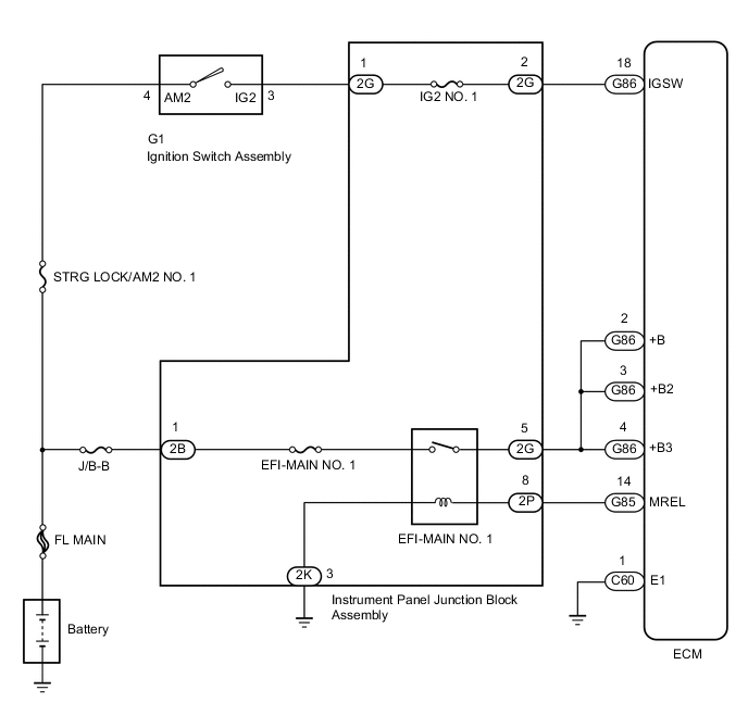
DESCRIPTION
When the ignition switch is turned to ON, the battery voltage is applied to terminal IGSW of the ECM. The MREL output signal from ECM causes a current to flow to the coil, closing the contacts of the EFI-MAIN NO. 1 relay and supplying power to terminal +B of the ECM.
CAUTION / NOTICE / HINT
-
Inspect the fuses of circuits related to this system before performing the following inspection procedure.
-
After replacing the ECM, the new ECM needs registration (Click here ) and initialization (Click here).
PROCEDURE
- Click here
INSPECT ECM (+B VOLTAGE)
-
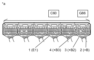
*a Component with harness connected
(ECM)
Turn the ignition switch to ON.
-
Measure the voltage according to the value(s) in the table below.
Standard Voltage Tester Connection Condition Specified Condition G86-2 (+B) - C60-1 (E1) Ignition switch ON 11 to 14 V G86-3 (+B2) - C60-1 (E1) Ignition switch ON 11 to 14 V G86-4 (+B3) - C60-1 (E1) Ignition switch ON 11 to 14 V Result Proceed to OK NG
- OK
PROCEED TO NEXT SUSPECTED AREA SHOWN IN PROBLEM SYMPTOMS TABLEClick here
- NGClick here
-
- Click here
CHECK HARNESS AND CONNECTOR (ECM - BODY GROUND)
-
Disconnect the ECM connector.
-
Measure the resistance according to the value(s) in the table below.
Standard Resistance Tester Connection Condition Specified Condition C60-1 (E1) - Body ground Always Below 1 Ω Result Proceed to OK NG
- OKClick here
- NG
REPAIR OR REPLACE HARNESS OR CONNECTOR
-
- Click here
INSPECT ECM (IGSW VOLTAGE)
-
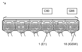
*a Component with harness connected
(ECM)
Turn the ignition switch to ON.
-
Measure the voltage according to the value(s) in the table below.
Standard Voltage Tester Connection Switch Condition Specified Condition G86-18 (IGSW) - C60-1 (E1) Ignition switch ON 11 to 14 V Result Proceed to OK NG (w/ Entry and Start System) NG (w/o Entry and Start System)
- OKClick here
- NG (w/o Entry and Start System)Click here
- NG (w/ Entry and Start System)Click here
-
- Click here
INSPECT ECM (MREL VOLTAGE)
-
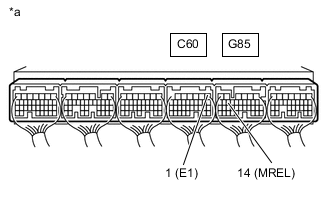
*a Component with harness connected
(ECM)
Turn the ignition switch to ON.
-
Measure the voltage according to the value(s) in the table below.
Standard Voltage Tester Connection Switch Condition Specified Condition G86-14 (MREL) - C60-1 (E1) Ignition switch ON 11 to 14 V Result Proceed to OK NG
- OKClick here
- NG
REPLACE ECMClick here
-
- Click here
INSPECT INSTRUMENT PANEL JUNCTION BLOCK ASSEMBLY (EFI-MAIN NO. 1 RELAY)
-
Inspect the instrument panel junction block assembly (EFI-MAIN NO. 1 relay).
Result Proceed to OK NG
- OKClick here
- NG
REPLACE INSTRUMENT PANEL JUNCTION BLOCK ASSEMBLY
-
- Click here
CHECK HARNESS AND CONNECTOR (INSTRUMENT PANEL JUNCTION BLOCK ASSEMBLY - ECM, INSTRUMENT PANEL JUNCTION BLOCK ASSEMBLY - BODY GROUND)
-
Remove the instrument panel junction block assembly connector.
-
Disconnect the ECM connector.
-
Measure the resistance according to the value(s) in the table below.
Standard Resistance Tester Connection Condition Specified Condition 2G-5 - G86-2 (+B) Always Below 1 Ω 2G-5 - G86-3 (+B2) Always Below 1 Ω 2G-5 - G86-4 (+B3) Always Below 1 Ω 2P-8 - G85-14 (MREL) Always Below 1 Ω 2K-3 - Body ground Always Below 1 Ω 2G-5 or G86-2 (+B) - Body ground and other terminals Always 10 kΩ or higher 2G-5 or G86-3 (+B2) - Body ground and other terminals Always 10 kΩ or higher 2G-5 or G86-4 (+B3) - Body ground and other terminals Always 10 kΩ or higher 2P-8 or G85-14 (MREL) - Body ground and other terminals Always 10 kΩ or higher Result Proceed to OK NG
- OK
REPAIR OR REPLACE HARNESS OR CONNECTOR (BATTERY - INSTRUMENT PANEL JUNCTION BLOCK ASSEMBLY)
- NG
REPAIR OR REPLACE HARNESS OR CONNECTOR
-
- Click here
INSPECT IGNITION SWITCH ASSEMBLY
-
Inspect the ignition switch assembly.
Result Proceed to OK NG
- OK
REPAIR OR REPLACE HARNESS OR CONNECTOR (BATTERY - IGNITION SWITCH ASSEMBLY, IGNITION SWITCH ASSEMBLY - ECM)
- NG
REPLACE IGNITION SWITCH ASSEMBLYClick here
-
- Click here
INSPECT IG2 RELAY
-
Inspect the IG2 relay.
Result Proceed to OK NG
- OKClick here
- NG
REPLACE IG2 RELAY
-
- Click here
CHECK HARNESS AND CONNECTOR (NO. 4 INSTRUMENT PANEL RELAY BLOCK - ECM)
-
Disconnect the ECM connector.
-
Remove the IG2 relay from No. 4 instrument panel relay block.
-
Measure the resistance according to the value(s) in the table below.
Standard Resistance Tester Connection Condition Specified Condition G86-18 (IGSW) - IG2 relay terminal 3 Always Below 1 Ω G86-18 (IGSW) or IG2 relay terminal 3 - Body ground and other terminals Always 10 kΩ or higher Result Proceed to OK NG
- OKClick here
- NG
REPAIR OR REPLACE HARNESS OR CONNECTOR
-
- Click here
CHECK TERMINAL VOLTAGE (IG2 RELAY)
-
Remove the IG2 relay from No. 4 instrument panel relay block.
-
Measure the voltage according to the value(s) in the table below.
Standard Voltage Tester Connection Switch Condition Specified Condition IG2 relay terminal 5 - Body ground Always 11 to 14 V Result Proceed to OK NG
- OKClick here
- NG
REPAIR OR REPLACE HARNESS OR CONNECTOR
-
- Click here
CHECK HARNESS AND CONNECTOR (CERTIFICATION ECU - NO. 4 INSTRUMENT PANEL RELAY BLOCK)
-
Disconnect the certification ECU (smart key ECU assembly) connector.
-
Remove the IG2 relay from No. 4 instrument panel relay block.
-
Measure the resistance according to the value(s) in the table below.
Standard Resistance Tester Connection Condition Specified Condition G69-20 (IG1D) - IG2 relay terminal 1 Always Below 1 Ω IG2 relay terminal 2 - Body ground Always Below 1 Ω G69-20 (IG1D) or IG2 relay terminal 1 - Body ground and other terminals Always 10 kΩ or higher Result Proceed to OK NG
- OK
CHECK ENTRY AND START SYSTEMClick here
- NG
REPAIR OR REPLACE HARNESS OR CONNECTOR
-