ECD SYSTEM(w/ Urea SCR System), Diagnostic DTC:P0617
| DTC Code | DTC Name |
|---|---|
| P0617 | Starter Relay Circuit High |
DESCRIPTION
While the engine is being cranked, the ECM detects the starter signal (STA signal) and performs engine control when the engine starts.
If the ECM detects the starter control (STA) signal while the vehicle is being driven, it determines that there is a malfunction in the STA circuit. The ECM then illuminates the MIL and stores the DTC.
This monitor runs when the vehicle has been driven at 20 km/h (12.5 mph) or more for more than 20 seconds.
| DTC No. | Detection Item | DTC Detection Condition | Trouble Area | MIL | Memory |
|---|---|---|---|---|---|
| P0617 | Starter Relay Circuit High | Conditions (a), (b) and (c) are met for 20 seconds (1 trip detection logic): (a) Vehicle speed is more than 20 km/h (12.5 mph). (b) Engine speed is more than 1000 rpm. (c) STA signal is on. |
|
Comes on | DTC stored |
*1: w/o Entry and Start System
*2: w/ Entry and Start System
| DTC No. | Data List |
|---|---|
| P0617 | Starter Signal |
CONFIRMATION DRIVING PATTERN
| DTC No. | DTC Detection Drive Pattern |
|---|---|
| P0617 | Drive the vehicle for 25 seconds or more at a speed of 20 km/h (12.5 mph) or more and an engine speed of 1000 rpm or more |
WIRING DIAGRAM
Figure 1. w/ Entry and Start System and w/ Stop and Start System
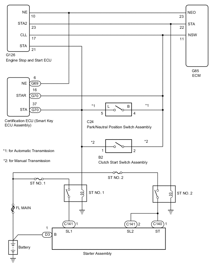
Figure 2. w/o Entry and Start System and w/ Stop and Start System
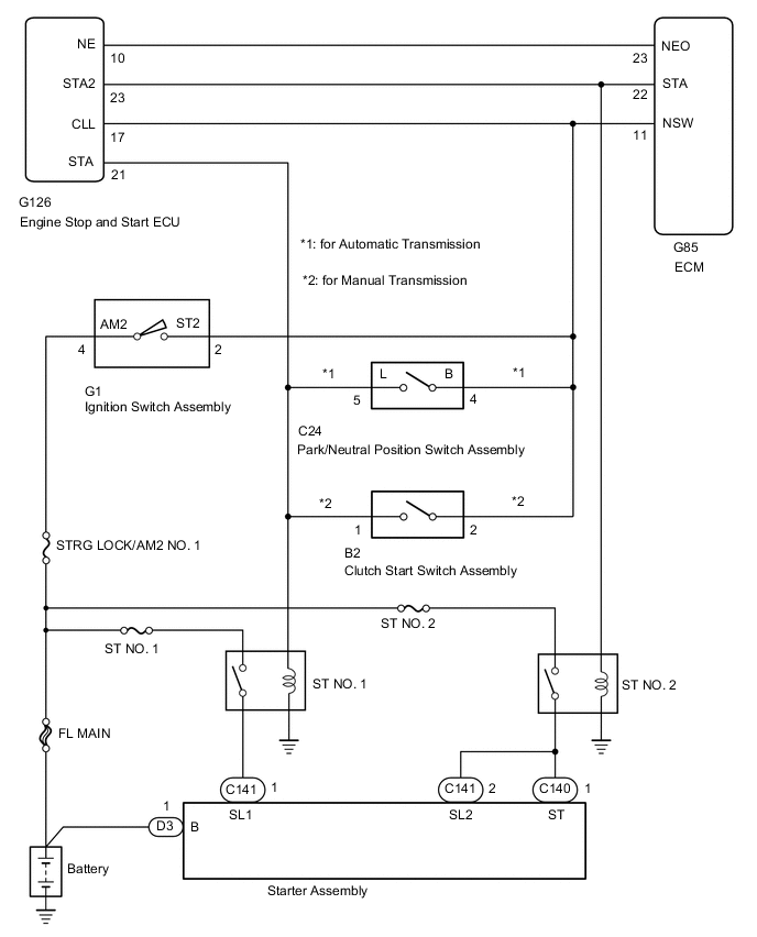
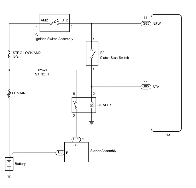
Figure 3. w/o Entry and Start System and w/o Stop and Start System
CAUTION / NOTICE / HINT
Note
-
Inspect the fuses of circuits related to this system before performing the following inspection procedure.
-
After replacing the ECM, the new ECM needs registration (Click here ) and initialization Click here.
-
Read Starter Count before replacing the engine stop and start ECU, perform the replacement procedure, and then write Starter Count to the newly installed engine stop and start ECU.
-
When replacing the engine stop and start ECU or the air conditioning amplifier assembly, initialize and learn the engine stop and start ECU air conditioning information.
-
When replacing the engine stop and start ECU or airbag ECU assembly (G sensor), initialize and learn the engine stop and start ECU G sensor zero point learned information.
Tech Tips
-
The following troubleshooting process is based on the premise that the engine can crank normally. If the engine does not crank, proceed to Problem Symptoms Table Click here.
-
If this DTC is output, inspect the starter assembly.
-
Read freeze frame data using the GTS. Freeze frame data records the engine condition when malfunctions are detected. When troubleshooting, freeze frame data can help determine if the vehicle was moving or stationary, if the engine was warmed up or not, and other data from the time the malfunction occurred.
PROCEDURE
-
READ VALUE USING GTS (STARTER SIGNAL)
-
Connect the GTS to the DLC3.
-
Turn the ignition switch to ON and turn the GTS on.
-
Enter the following menus: Powertrain / Engine / Data List / Starter Signal.
Powertrain > Engine > Data ListTester Display Starter Signal -
Read the value displayed on the GTS when the vehicle is driven at 20 km/h (12.4 mph) or more with engine speed at 1000 rpm or more.
Result Result Proceed to Driving at 20 km/h (12.4 mph) or more with engine speed at 1000 rpm or more OFF A ON w/ Stop and Start System B w/o Stop and Start System C
A 
CHECK FOR INTERMITTENT PROBLEMS Click here
C 
INSPECT CLUTCH START SWITCH Click here
B 
-
-
INSPECT ENGINE STOP AND START ECU
-
Start the engine.
-
Measure the voltage according to the value(s) in the table below.
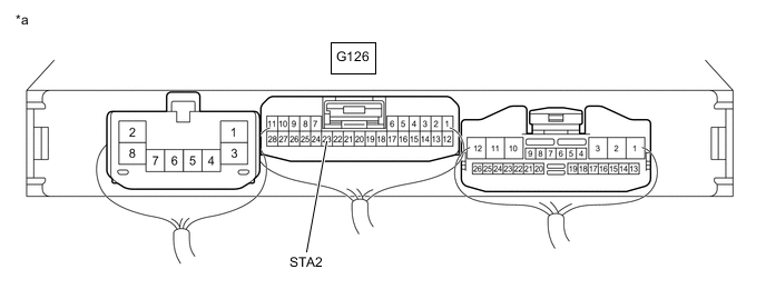
*a Component with harness connected
(Engine Stop and Start ECU)
- - Standard Voltage Tester Connection Condition Specified Condition G126-23 (STA2) - Body ground Vehicle driving (Engine speed of 1000 rpm or more and vehicle speed at 20 km/h (12.4 mph) or more) 0 to 1.5 V Result Proceed to OK NG
NG
REPLACE ENGINE STOP AND START ECU Click here
OK
-
-
REPAIR OR REPLACE HARNESS OR CONNECTOR (STA SIGNAL CIRCUIT)
-
Repair or replace the harness or connector (STA signal circuit).
Result Proceed to NEXT
NEXT
-
-
CHECK WHETHER DTC OUTPUT RECURS (DTC P0617)
-
Connect the GTS to the DLC3.
-
Turn the ignition switch to ON and turn the GTS on.
-
Clear the DTCs.
-
Turn the ignition switch off and wait for at least 30 seconds.
-
Drive the vehicle for 25 seconds or more at a speed of 20 km/h (12.4 mph) or more and an engine speed of 1000 rpm or more.
-
Enter the following menus: Powertrain / Engine / Trouble Codes.
-
Read the DTCs.
Powertrain > Engine > Trouble CodesResult Result Proceed to DTC P0617 is output A DTCs are not output B
A
REPLACE ECM Click here
B
END
-
-
INSPECT CLUTCH START SWITCH
-
Inspect the clutch start switch.
Result Proceed to OK NG
NG
REPLACE CLUTCH START SWITCH ASSEMBLY Click here
OK
-
-
INSPECT IGNITION SWITCH ASSEMBLY
-
Inspect the ignition switch assembly.
Result Proceed to OK NG
NG
REPLACE IGNITION SWITCH ASSEMBLY Click here
OK
-
-
REPAIR OR REPLACE HARNESS OR CONNECTOR (STA SIGNAL CIRCUIT)
-
Repair or replace the harness or connector (STA signal circuit).
Result Proceed to NEXT
NEXT
GO TO STEP 4 Click here
-
-
REPLACE IGNITION SWITCH ASSEMBLY
-
Replace the ignition switch assembly.
Result Proceed to NEXT
NEXT
-
-
CONFIRM WHETHER DTC OUTPUT RECURS
-
Connect the GTS to the DLC3.
-
Clear the DTCs.
-
Turn the ignition switch off.
-
Turn the ignition switch to ON.
-
Drive the vehicle for 25 seconds or more at a speed of 20 km/h (12.4 mph) or more and an engine speed of 1000 rpm or more.
-
Enter the following menus: Powertrain / Engine / Trouble Codes.
-
Confirm that the DTC is not output again.
Powertrain > Engine > Trouble CodesResult Proceed to NEXT
NEXT
END
-
-
REPLACE CLUTCH START SWITCH ASSEMBLY
-
Replace the clutch start switch assembly.
Result Proceed to NEXT
NEXT
GO TO STEP 9 Click here
-