| DTC Code | DTC Name |
|---|---|
| P1251 | Step Motor for Turbocharger Control Circuit (Intermittent) |
DESCRIPTION
Refer to DTC P0046.
| DTC No. | Detection Item | DTC Detection Condition | Trouble Area | MIL | Memory |
|---|---|---|---|---|---|
| P1251 | Step Motor for Turbocharger Control Circuit (Intermittent) | Boost pressure is higher than the threshold* for 5 seconds (1 trip detection logic).
Tip:
*: This value changes based on engine speed, atmospheric pressure and the engine coolant temperature (the value is generally between 90 and 276 kPa). |
|
Comes on | DTC stored |
| DTC No. | Data List |
|---|---|
| P1251 |
|
If DTC P1251 is stored due to the VN turbo vane being stuck closed, the following symptoms may appear:
-
Vehicle surge when driving with full load
-
Sudden lack of power due to power being limited
CONFIRMATION DRIVING PATTERN
| DTC No. | DTC Detection Drive Pattern |
|---|---|
| P1251 | Vehicle being driven |
CAUTION / NOTICE / HINT
After replacing an injector assembly, the ECM needs registration (Click here).
Read freeze frame data using the GTS. Freeze frame data records the engine condition when malfunctions are detected. When troubleshooting, freeze frame data can help determine if the vehicle was moving or stationary, if the engine was warmed up or not, and other data from the time the malfunction occurred.
PROCEDURE
- Click here
CHECK FOR ANY OTHER DTCS OUTPUT (RECORD STORED DTC AND FREEZE FRAME DATA)
-
Connect the GTS to the DLC3.
-
Turn the ignition switch to ON and turn the GTS on.
-
Enter the following menus: Powertrain / Engine / Trouble Codes.
-
Read the DTCs.
- Powertrain > Engine > Trouble Codes
-
-
Tip:
-
Record the stored DTCs and freeze frame data.
-
Be sure to carefully examine "MAP" and "Target Booster Pressure" in the freeze frame data.
Result Result Proceed to DTC P1251 is output A DTC P1251 and other DTCs are output B Tip:Variable vane DC motor-related DTCs: P0046, P0047 and P0048.
Nozzle vane position sensor-related DTCs: P2564 and P2565.
- AClick here
- B
GO TO DTC CHARTClick here
-
- Click here
CHECK INTAKE SYSTEM
-
Check if the hoses between the air cleaner filter element sub-assembly and turbocharger sub-assembly, and turbocharger sub-assembly and intake manifold are damaged or disconnected.
Result Result Proceed to Hoses or pipes are damaged or disconnected A No hoses or pipes are damaged or disconnected B Tip:
-
Be sure to check if the hoses and pipes between the air cleaner and compressor are disconnected as disconnection of a hose or pipe can cause overboost. Also, check the high pressure hoses for disconnection due to overboost.
-
Check for disconnection of the exhaust pipes.
-
Using your hand, check whether the pipes and hoses in the intake system are securely connected.
-
Check for any modifications in the intake system made by the user.
-
- AClick here
- BClick here
GO TO STEP 4
-
- Click here
REPAIR OR REPLACE INTAKE SYSTEM
-
Repair or replace the malfunctioning part in the intake system.
Result Proceed to NEXT
- NEXTClick here
-
- Click here
PERFORM ACTIVE TEST USING GTS (OPERATE TURBOCHARGER SUB-ASSEMBLY)
-
Connect the GTS to the DLC3.
-
Turn the ignition switch to ON and turn the GTS on.
-
Enter the following menus: Powertrain / Engine / Active Test / Test the Turbo Charger Step Motor / Data List / Target VN Turbo Position and Actual VN Turbo Position.
- Powertrain > Engine > Active Test
Active Test Display Test the Turbo Charger Step Motor Data List Display Target VN Turbo Position Actual VN Turbo Position -
-
-
-
- Powertrain > Engine > Active Test
-
While changing the Active Test value to 10, 20, 30, 40, 30, 20 and 10%, check that Actual VN Turbo Position smoothly changes to the set opening amount.
Note:When moving the vanes toward the fully closed position, make sure that Actual VN Turbo Position does not become 5% or less.
OK The Actual VN Turbo Position value follows the Target VN Turbo Position. Result Proceed to OK NG
- OKClick here
- NGClick here
-
- Click here
PERFORM ACTIVE TEST USING GTS (ACTIVATE THE EGR VALVE CLOSE)
-
Connect the GTS to the DLC3.
-
Start the engine and warm it up, and make sure the A/C switch and all accessory switches are off.
-
Turn the ignition switch off. Wait for 30 seconds, and then restart the engine.
-
Turn the GTS on.
-
Enter the following menus: Powertrain / Engine / Data List / MAF.
- Powertrain > Engine > Data List
Tester Display MAF -
-
-
-
- Powertrain > Engine > Data List
-
Read the MAF value displayed on the GTS while the engine is idling.
-
Enter the following menus: Powertrain / Engine / Active Test / Activate the EGR Valve Close / Data List / MAF.
- Powertrain > Engine > Active Test
Active Test Display Activate the EGR Valve Close Data List Display MAF -
-
-
-
- Powertrain > Engine > Active Test
-
Read the MAF value when the EGR valve is closed using the Active Test function.
Tip:
-
If idling continues for 20 minutes or more, the EGR valve target opening angle becomes 0% (EGR valve fully closed). As this makes diagnosis impossible, it becomes necessary to drive the vehicle or to restart the engine.
-
Before performing the diagnosis, confirm that the EGR valve target opening angle is not 0%.
-
When idling the engine, the EGR cooler is bypassed.
Result Active Test Result Proceed to Activate the EGR Valve Close:
Off (Open) to On (Closed)
MAF value does not change A MAF value changes B Note:As the measured values may differ from those shown below due to factors such as differences in measuring environments and changes in vehicle condition due to aging, do not use these values to determine whether the vehicle is malfunctioning or not.
Tip:The problem may be a temporary one, due to the entry of deposits or foreign matter. Check that there are no deposits or foreign matter in the electric EGR control valve assembly or mass air flow meter sub-assembly.
Reference EGR Valve Condition (Opening) Measuring Condition MAF (Reference) Open (50%)
-
Atmospheric pressure: 101 kPa
-
Engine coolant temperature: 75°C (167°F)
3 to 10 gm/sec Closed (0%) 12 to 18 gm/sec -
-
- Click here
READ VALUE USING GTS (TARGET EGR VALVE POS AND ACTUAL EGR VALVE POS)
-
Check the change in the values of "Target EGR Valve Pos" and "Actual EGR Valve Pos" in the Data List from the time when the "Control the EGR Step Position" Active Test was performed in the previous step.
Result Result Proceed to Even though "Target EGR Valve Pos" indicated that the system was commanding the valve to open, "Actual EGR Valve Pos" remained near 0% and did not change A Other than above ("Actual EGR Valve Pos" changed according to the EGR valve open/close commands of the Active Test) B
-
- Click here
CHECK FOR DEPOSIT (ELECTRIC EGR CONTROL VALVE ASSEMBLY)
-
Remove the electric EGR control valve assembly.
-
Visually check the electric EGR control valve assembly for deposits. If there are deposits, clean the electric EGR control valve assembly.
Note:
-
When cleaning the electric EGR control valve assembly, make sure the valve is completely closed.
-
Do not forcibly open the valve, as it may be damaged or deformed.
-
When cleaning the electric EGR control valve, use a piece of cloth soaked with cleaning solvent. Spraying the solvent directly onto these parts or soaking the parts in the solvent may damage the parts.
-
When cleaning the electric EGR control valve, care should be taken to prevent the ingress of cleaning solvent into the bearings of the valve shaft, and when wiping off deposits on the EGR valve, care should be taken not to push the deposits into the bearings of the valve shaft. These contaminants may adversely affect the function of the EGR valve.
-
When cleaning the electric EGR control valve assembly, perform the initialization procedure.
Tip:
-
If the EGR valve does not open properly or is stuck closed, the amount of intake air increases and combustion sounds and engine vibration may increase.
-
If the EGR valve does not close properly or is stuck open, EGR becomes excessive and combustion becomes unstable. Also, there may be a lack of power.
-
-
Reinstall the electric EGR control valve assembly.
Result Proceed to NEXT
- NEXTClick here
GO TO STEP 13
-
- Click here
REPLACE NO. 1 EGR COOLER
-
Replace the No. 1 EGR cooler.
Result Proceed to NEXT
- NEXTClick here
GO TO STEP 13
-
- Click here
READ VALUE USING GTS (INJECTION VOLUME)
-
Connect the GTS to the DLC3.
-
Start the engine and warm it up until the engine coolant temperature reaches 75°C (167°F) or higher.
-
Allow the engine to idle for 1 minute or more.
Tip:The A/C switch and all accessory switches should be off with a fully warm engine.
-
Turn the GTS on.
-
Enter the following menus: Powertrain / Engine / Data List / Primary / Injection Volume.
- Powertrain > Engine > Data List
Tester Display Injection Volume -
-
-
-
- Powertrain > Engine > Data List
-
Read the value of Injection Volume at 4000 rpm without load.
Result Result Proceed to Injection Volume is less than 8.0 mm3/st
A Except above B Tip:
-
If the injector assembly is malfunctioning, the compensatory injection volume remains at 5.0 mm3/st.
-
If there is a disconnection, the feedback value will increase and +5.0 mm3/st will be indicated, because it will become impossible for the injector to inject.
-
- AClick here
- BClick here
GO TO STEP 13
-
- Click here
REPLACE INJECTOR ASSEMBLIES OF ALL CYLINDERS
-
Replace the injector assemblies of all cylinders.
Note:
-
When replacing the injector assembly for a cylinder, always be sure to use a new No. 1 injection pipe sub-assembly and a new No. 2 injection pipe sub-assembly.
-
Follow the procedure in the repair manual and temporarily install the No. 1 injection pipe sub-assembly, No. 2 injection pipe sub-assembly and No. 1 nozzle leakage pipe assembly, and then correctly position the injector assemblies. After that, tighten parts according to the torque specifications.
-
If the installation procedure is not performed correctly, injector assemblies may become out of position, which may cause the injector assemblies to deteriorate, resulting in malfunctions.
-
If an injector assembly deteriorates and malfunctions, other problems such as knocking, rough idle, etc. may occur.
-
If an injector assembly becomes out of position, it is possible that the seal between the injector assembly and injection pipe sub-assembly may become incomplete, resulting in a fuel leak.
Result Proceed to NEXT -
- NEXTClick here
-
- Click here
BLEED AIR FROM FUEL SYSTEM
-
Bleed the air from the fuel system.
Result Proceed to NEXT
- NEXTClick here
-
- Click here
REGISTER INJECTOR COMPENSATION CODE AND PERFORM PILOT QUANTITY LEARNING
-
Register the injector compensation code.
- Powertrain > Engine > Utility
Tester Display Injector Compensation -
-
-
-
- Powertrain > Engine > Utility
-
Perform the injector pilot quantity learning.
- Powertrain > Engine > Utility
Tester Display Pilot Quantity Learning -
-
-
-
Result Proceed to NEXT - Powertrain > Engine > Utility
- NEXTClick here
-
- Click here
CONFIRM WHETHER MALFUNCTION HAS BEEN SUCCESSFULLY REPAIRED
-
Connect the GTS to the DLC3.
-
Clear the DTCs.
- Powertrain > Engine > Clear DTCs
-
-
-
Turn the ignition switch off.
-
Start the engine and warm it up.
-
Confirm the value of Engine Speed from the Freeze Frame Data recorded previously, and then drive the vehicle according to the Engine Speed value.
Tip:Take a snapshot of "MAP" and "Target Boost Pressure" in the Data List with the GTS while driving the vehicle.
-
Enter the following menus: Powertrain / Engine / Trouble Codes.
-
Read the DTCs.
- Powertrain > Engine > Trouble Codes
-
-
Result Result Proceed to DTC P1251 is not output and the amount by which MAP exceeds Target Boost Pressure is 20 kPa or less A Except above B* Tip:*: Return to "Check Intake System" and inspect areas that have not been inspected yet.
- A
END
- B*Click here
GO TO STEP 2
-
- Click here
CHECK HARNESS AND CONNECTOR (TURBOCHARGER NOZZLE VANE CONTROL ACTUATOR - ECM)
-
Disconnect the variable vane DC motor connector.
-
Disconnect the nozzle vane position sensor connector.
-
Disconnect the ECM connector.
-
Measure the resistance according to the value(s) in the table below.
Standard Resistance Tester Connection Condition Specified Condition C91-1 (M-) - C59-2 (VNM-) Always Below 1 Ω C91-2 (M+) - C59-1 (VNM+) Always Below 1 Ω C93-3 (VTA1) - C59-23 (VNA) Always Below 1 Ω C93-2 (VNE2) - C59-22 (VNE2) Always Below 1 Ω C93-1 (VNVC) - C59-30 (VNVC) Always Below 1 Ω C91-1 (M-) or C59-2 (VNM-) - Body ground and other terminals Always 10 kΩ or higher C91-2 (M+) or C59-1 (VNM+) - Body ground and other terminals Always 10 kΩ or higher C93-3 (VTA1) or C59-23 (VNA) - Body ground and other terminals Always 10 kΩ or higher C93-1 (VNVC) or C59-30 (VNVC) - Body ground and other terminals Always 10 kΩ or higher Result Proceed to OK NG
- OKClick here
- NG
REPAIR OR REPLACE HARNESS OR CONNECTOR
-
- Click here
INSPECT TURBOCHARGER NOZZLE VANE PLATE
-
Remove the turbocharger sub-assembly.
-
Inspect the turbocharger nozzle vane plate.
-
Remove the e-washer from the turbocharger nozzle vane control actuator.
-
-
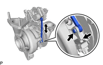
Move the turbocharger vane control rod sub-assembly and check that the turbocharger nozzle vane support plate moves.
Result Result Proceed to Catches, but operates* OK Gets stuck and does not operate NG Tip:*: Check several times.
- OK
REPLACE TURBOCHARGER NOZZLE VANE CONTROL ACTUATORClick here
- NG
REPLACE TURBOCHARGER SUB-ASSEMBLYClick here
-