ECD SYSTEM(w/ Urea SCR System), Diagnostic DTC:P0420, P244A, P244B, P2458, P2463
| DTC Code | DTC Name |
|---|---|
| P0420 | Catalyst System Efficiency Below Threshold (Bank 1) |
| P244A | Diesel Particulate Filter Differential Pressure Too Low |
| P244B | Diesel Particulate Filter Differential Pressure Too High |
| P2458 | Diesel Particulate Filter Regeneration Duration |
| P2463 | Diesel Particulate Filter Restriction - Soot Accumulation |
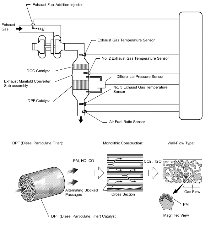
DESCRIPTION
DPF (Diesel Particulate Filter) is an emission control system which processes the particulate matter (PM) that is emitted from a diesel engine. The DPF catalyst has a porous ceramic structure which has a PM collecting function. The PM that is collected is continuously treated by oxidation due to catalytic action at high temperatures, however PM accumulation increases at low catalyst temperatures because the oxidation process slows down. The ECM performs PM forced regeneration so that the amount of accumulated PM does not exceed the threshold.
| DTC No. | Detection Item | DTC Detection Condition | Trouble Area | MIL | Memory |
|---|---|---|---|---|---|
| P0420 | Catalyst System Efficiency Below Threshold (Bank 1) | During PM forced regeneration, DOC catalyst temperature does not increase sufficiently for 3 minutes (2 trip detection logic). |
Common Inspection Item:
|
Comes on | DTC stored |
| P244A | Diesel Particulate Filter Differential Pressure Too Low | When driving, the catalyst differential pressure is continuously below the threshold for 7 seconds or more (2 trip detection logic). |
Common Inspection Item:
|
Comes on | DTC stored |
| P244B | Diesel Particulate Filter Differential Pressure Too High | While driving, Catalyst Differential Pressure becomes more than 0.45 for 3 seconds (1 trip detection logic). |
Common Inspection Item:
|
Comes on | DTC stored |
| P2458 | Diesel Particulate Filter Regeneration Duration | When PM forced regeneration is manually performed, PM forced regeneration does not finish even after 60 minutes or more elapse (1 trip detection logic). |
Common Inspection Item:
|
Comes on | DTC stored |
| P2463 | Diesel Particulate Filter Restriction - Soot Accumulation | While driving, PM accumulation amount exceeds the limit (1 trip detection logic). |
Common Inspection Item:
|
Comes on | DTC stored |
Tech Tips
PM forced regeneration may be prohibited due to a fail-safe operation that is performed when another DTC is stored (including engine output limitation).
| DTC No. | Data List |
|---|---|
| P0420 P244A P244B P2458 P2463 |
|
MONITOR DESCRIPTION
The ECM monitors the differential pressure between the upstream and downstream of the DPF catalyst and also monitors exhaust gas temperature to detect a malfunction in the exhaust manifold converter sub-assembly.
-
The ECM monitors exhaust gas temperature increase while the exhaust fuel addition injector assembly adds fuel during PM forced regeneration. Exhaust gas temperature increases up to approximately 300 to 500°C (572 to 932°F) during PM forced regeneration. If the temperature does not increase even after a certain amount of time has elapsed, the ECM determines that the DOC catalyst is abnormal and illuminates the MIL.
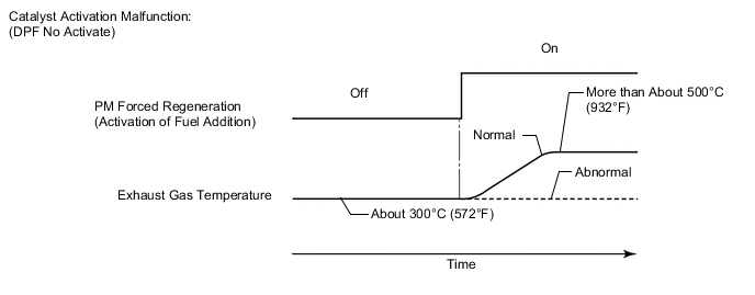
Abnormal DOC catalyst temperature increase:
-
The ECM monitors the DPF catalyst differential pressure when driving and illuminates the MIL when the difference in pressure before and after the catalyst is below the threshold.
Catalytic converter differential pressure too low:
-
The ECM compares pressure upstream and downstream of the DPF catalyst to monitor the differential pressure. If the differential pressure is large, the ECM determines that the DPF catalyst is contaminated or has deteriorated and illuminates the MIL.
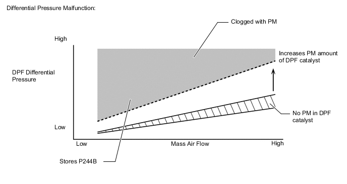
Catalytic converter differential pressure too high:
-
When PM forced regeneration is manually performed, PM forced generation does not finish even after 60 minutes or more elapse, the ECM determines that there is problem with the DPF catalyst and illuminates the MIL.
Catalytic converter regeneration duration:
-
The ECM monitors the PM Accumulation Ratio and when the accumulated PM volume in the DPF catalyst exceeds the limit, the ECM illuminates the MIL.
Excessive PM accumulation:
CONFIRMATION DRIVING PATTERN
| DTC No. | DTC Detection Drive Pattern |
|---|---|
| P0420 P244A P2458 P2463 |
PM forced regeneration |
| P244B | Engine is running at 4000 rpm with no load for 10 seconds or more. |
CAUTION / NOTICE / HINT
Note
-
After replacing the ECM, the new ECM needs registration (Click here) and initialization Click here.
-
After replacing an injector assembly, the ECM needs registration.
-
After turning ignition switch off, waiting time may be required before disconnecting the cable from the negative (-) battery terminal. Therefore, make sure to read the disconnecting the cable from the negative (-) battery terminal notices before proceeding with work.
Tech Tips
-
If DTC P2458 or P2463 is stored, fail-safe controls engine power output and PM forced regeneration is prohibited. In this case, PM forced regeneration can be performed after disconnecting the EFI-B fuse or battery terminal and waiting for 60 seconds or more before connecting it again.
-
Read freeze frame data using the GTS. Freeze frame data records the engine condition when malfunctions are detected. When troubleshooting, freeze frame data can help determine if the vehicle was moving or stationary, if the engine was warmed up or not, and other data from the time the malfunction occurred.
PROCEDURE
-
READ DTC OUTPUT (RECORD STORED DTC AND FREEZE FRAME DATA)
-
Connect the GTS to the DLC3.
-
Turn the ignition switch to ON.
-
Turn the GTS on.
-
Enter the following menus: Powertrain / Engine / Trouble Codes.
-
Record the stored DTC and freeze frame data.
Powertrain > Engine > Trouble Codes -
Check Exhaust Fuel Addition FB and Catalyst Differential Press in the freeze frame data.
Tech Tips
-
When the Exhaust Fuel Addition FB value is 1.45 or more, it indicates a high possibility of insufficient temperature increase during PM regeneration control.
-
When the Catalyst Differential Press value is more than 0.45, it indicates a high possibility that DPF catalyst is clogged.
Result Proceed to NEXT -
NEXT 
-
-
CHECK ANY OTHER DTCS OUTPUT (IN ADDITION TO DTC P0420, P244A, P244B, P2458 AND P2463)
-
Connect the GTS to the DLC3.
-
Turn the ignition switch to ON.
-
Turn the GTS on.
-
Enter the following menus: Powertrain / Engine / Trouble Codes.
-
Read the DTCs.
Powertrain > Engine > Trouble CodesResult Result Proceed to DTC P244A is output A DTC P244B is output B DTC P244B is output at the same time as P2463 DTC P0420, P2458 or P2463 is output C Other relevant DTCs are output D Tech Tips
When DTC P1603, P1604 or P1608 is output in addition to P0420, perform troubleshooting for P1603, P1604 or P1608 first.
C 
GO TO STEP 11 Click here
D
GO TO DTC CHART Click here
B
READ VALUE USING GTS (DPF DIFFERENTIAL PRESSURE) Click here
A
-
-
CHECK BLOCKAGE OF AIR HOSE AND VACUUM PIPE (DIFFERENTIAL PRESSURE SENSOR - VACUUM PIPE)
CAUTION:
Be careful of being burned by exhaust gases during the following inspection.
Tech Tips
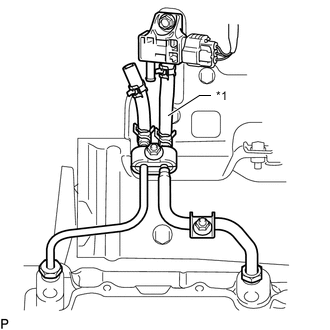
Before checking the differential pressure sensor, perform a visual inspection of the differential pressure pipes and check that they are properly connected and no air is leaking from the pipes or hoses. If a malfunction is found, repair it before checking the sensor.
-
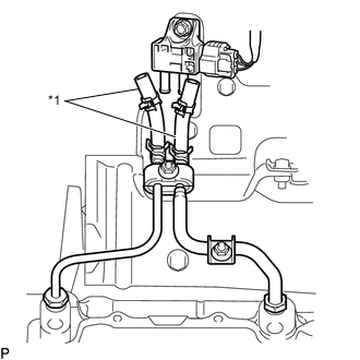
*1 Air Hose Disconnect the air hoses (both upstream and downstream) from the differential pressure sensor.
-
Start the engine.
-
Check if there are exhaust gas pulsations from both air hoses during idling.
OK Exhaust gas pulsation exists. Result Proceed to OK NG
NG
REPAIR OR REPLACE NO. 1 VACUUM PIPE OR NO. 2 VACUUM PIPE Click here
OK
-
-
READ VALUE USING GTS (DPF DIFFERENTIAL PRESSURE)
-
Connect the GTS to the DLC3.
-
Turn the ignition switch to ON and turn the GTS on.
-
Enter the following menus: Powertrain / Engine / Data List / DPF Differential Pressure.
-
Check that the differential pressure is as specified below.
Powertrain > Engine > Data ListTester Display DPF Differential Pressure OK Approximately 0 kPa Result Proceed to OK NG
NG
GO TO STEP 6 Click here
OK
-
-
CONNECT UPSTREAM AIR HOSE
-
*1 Air Hose (Upstream) Connect the upstream air hose to the differential pressure sensor.
-
Connect the GTS to the DLC3.
-
Turn the ignition switch to ON and turn the GTS on.
-
Enter the following menus: Powertrain / Engine / Data List / DPF Differential Pressure.
-
Start the engine.
-
Engine is running at 4000 rpm with no load for 10 seconds or more.
-
Check that the differential pressure is as specified below.
Powertrain > Engine > Data ListTester Display DPF Differential Pressure Result DPF Differential Pressure Proceed to 1.5 kPa or higher A Below 1.5 kPa B
A
GO TO STEP 7 Click here
B
-
-
REPLACE DIFFERENTIAL PRESSURE SENSOR
-
Replace the differential pressure sensor.
Result Proceed to NEXT
NEXT
-
-
CONNECT DOWNSTREAM AIR HOSE
-
Connect the downstream air hose to the differential pressure sensor.
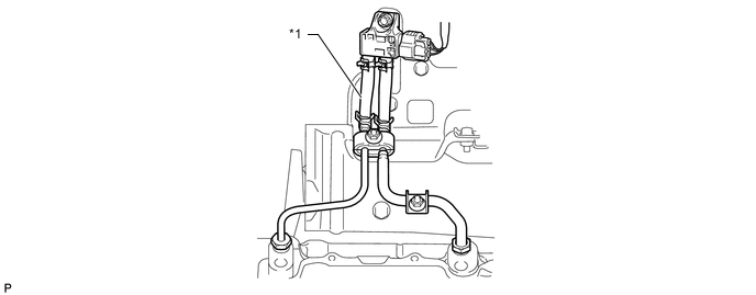
*1 Air Hose (Downstream) - - -
Connect the GTS to the DLC3.
-
Turn the ignition switch to ON and turn the GTS on.
-
Enter the following menus: Powertrain / Engine / Data List / DPF Differential Pressure.
-
Start the engine.
-
Engine is running at 4000 rpm with no load for 10 seconds or more.
-
Check that the differential pressure is as specified below.
Powertrain > Engine > Data ListTester Display DPF Differential Pressure Result DPF Differential Pressure Proceed to -1.5 to 1.5 kPa A Higher than 1.5 kPa B
B
GO TO STEP 11 Click here
A
-
-
REPLACE EXHAUST MANIFOLD CONVERTER SUB-ASSEMBLY
-
It has been determined that the exhaust manifold converter sub-assembly needs to be replaced. However, perform all the troubleshooting procedures before replacing the exhaust manifold converter sub-assembly.
Tech Tips
If the differential pressure before and after the DPF is low, it is very likely that there is no DPF or the material inside the DPF is missing due to erosion, etc. If the DPF catalyst is eroded, do not replace the DPF at this time, as troubleshooting the cause and other repairs are necessary.
Result Proceed to NEXT
NEXT
GO TO STEP 13 Click here
-
-
REPAIR OR REPLACE NO. 1 VACUUM PIPE OR NO. 2 VACUUM PIPE
-
Repair or replace No. 1 vacuum pipe or No. 2 vacuum pipe.
Result Proceed to NEXT
NEXT
GO TO STEP 4 Click here
-
-
GO TO DTC CHART
-
Diagnose relevant DTCs.
Result Proceed to NEXT
NEXT
-
-
CHECK FOR BLACK SMOKE
-
Start the engine and drive the vehicle until the engine coolant temperature reaches 75°C (167°F) or higher.
-
Stop the vehicle and allow the engine to idle.
-
Fully depress the accelerator pedal for 5 seconds, and then release it [A].
-
Repeat the procedure [A] 10 times [B].
-
Check for black smoke emission during the procedures [A] and [B].
OK Black smoke is emitted less than 5 times. Tech Tips
Even if the black smoke is very thin, count the number of black smoke emissions if there is any visible smoke.
Result Proceed to OK NG
OK
CHECK FOR WHITE SMOKE (DURING PM FORCED REGENERATION) Click here
NG
-
-
REPLACE EXHAUST MANIFOLD CONVERTER SUB-ASSEMBLY
-
It has been determined that the exhaust manifold converter sub-assembly needs to be replaced. However, perform all the troubleshooting procedures before replacing the exhaust manifold converter sub-assembly.
Tech Tips
This DTC is stored because an excessive amount of PM has accumulated and resulted in abnormal combustion. It is necessary to diagnose the cause of abnormal PM accumulation and repair the problem. Therefore, do not perform replacement at this time.
Result Proceed to NEXT
NEXT
-
-
CHECK FOR WHITE SMOKE (DURING PM FORCED REGENERATION)
-
Remove the EFI-B fuse or disconnect the cable from the battery terminal for 60 seconds or more, and then reinstall the EFI-B fuse or reconnect the cable to the battery terminal.
Tech Tips
-
The amount of built up particulate matter recorded by the ECM cannot be initialized by the GTS.
-
If the amount of built up particulate matter recorded by the ECM is not initialized, PM forced regeneration cannot be performed using the GTS.
-
-
Turn the ignition switch to ON.
-
Turn the ignition switch off and wait for 30 seconds or more.
-
Turn the ignition switch to ON and wait for 10 seconds or more.
-
Connect the GTS to the DLC3.
-
Turn the ignition switch to ON and turn the GTS on.
-
Start the engine and warm it up until the engine coolant temperature reaches 75°C (167°F) or higher.
-
Maintain the maximum possible engine speed under no load for 10 seconds to blow out all soot from inside the exhaust pipe.
Tech Tips
-
If only a low engine speed is continuously maintained, soot may accumulate at the end of the catalyst.
-
When soot accumulates at the end of the catalyst, it may not be possible to perform PM forced regeneration control normally.
-
-
Enter the following menus: Powertrain / Engine / Active Test / Activate the DPF Rejuvenate (PM) / Data List / Diesel Exhaust / Exhaust Temperature B1S2.
-
Perform the Active Test.
Powertrain > Engine > Active TestActive Test Display Activate the DPF Rejuvenate (PM) Data List Display Exhaust Temperature B1S2 CAUTION:
Be careful of the exhaust pipes and surrounding areas, as they become extremely hot when performing PM forced regeneration.
Tech Tips
When PM Accumulation Ratio is too low, Activate the DPF Rejuvenate (PM) cannot be performed. Therefore, rev the engine with no load at 3400 rpm for 5 to 10 minutes to increase PM Accumulation Ratio to 12% or more.
-
Check for temperature increases and abnormal white smoke during PM forced regeneration.
Tech Tips
-
PM forced regeneration takes 15 to 40 minutes to finish.
-
The time it takes to complete PM forced regeneration changes depending on "PM Accumulation Ratio" and the vehicle operating conditions.
-
If the value of "Catalyst Differential Press" increases too much during the PM forced regeneration, the fail-safe function activates and PM forced regeneration is stopped.
-
Perform PM forced regeneration control until the display on the multi-information display turns off.
-
If actions such as depressing the accelerator pedal or clutch pedal, etc. are performed during PM forced regeneration, PM forced regeneration stops. If PM forced regeneration stops, it is necessary to perform it again.
-
PM forced regeneration control is not complete until the display on the multi-information display turns off.
Result Result Proceed to During PM forced regeneration, temperature of Exhaust Temperature B1S2 is 300 to 500°C and no white smoke is generated A During PM forced regeneration, temperature of Exhaust Temperature B1S2 is 300 to 500°C and abnormal white smoke is generated*1 B Other than above*2 C Tech Tips
-
*1: If abnormal white smoke is only generated during PM forced regeneration, there may be uncombusted fuel due to deterioration of the DPF catalyst.
-
*1: When there is a malfunction with combustion control, operation performance may be reduced and abnormalities may be felt even if PM forced regeneration is performed.
-
*2: An excess of accumulated PM is the result of a malfunction in the control system causing poor combustion and an increase in black smoke.
-
B
REPLACE EXHAUST MANIFOLD CONVERTER SUB-ASSEMBLY Click here
C
CHECK FUEL INJECTION SYSTEM Click here
A
-
-
REPLACE EXHAUST FUEL ADDITION INJECTOR ASSEMBLY
-
It has been determined that the exhaust fuel addition injector assembly needs to be replaced. However, perform all the troubleshooting procedures before replacing the exhaust fuel addition injector assembly.
Result Proceed to NEXT
NEXT
GO TO STEP 16 Click here
-
-
REPLACE EXHAUST MANIFOLD CONVERTER SUB-ASSEMBLY
-
It has been determined that the exhaust manifold converter sub-assembly needs to be replaced. However, perform all the troubleshooting procedures before replacing the exhaust manifold converter sub-assembly.
Tech Tips
If abnormal white smoke is only generated during PM forced regeneration, there may be uncombusted fuel due to deterioration of the DPF catalyst. When there is a malfunction with combustion control, operation performance may be reduced and abnormalities may be felt even if PM forced regeneration is performed.
Result Proceed to NEXT
NEXT
-
-
CHECK FUEL INJECTION SYSTEM
-
Check the fuel injection system.
Result Proceed to NEXT
NEXT
-
-
CHECK INTAKE/EXHAUST SYSTEM
-
Check the intake/exhaust system.
Result Proceed to NEXT
NEXT
-
-
CHECK AFTER TREATMENT CONTROL SYSTEM
-
Check the after treatment control system.
Result Proceed to NEXT
NEXT
-
-
REPAIR OR REPLACE MALFUNCTIONING PARTS
Tech Tips
Replace the following items only when it has been determined necessary based on diagnosis for DTC P0420, P244A, P244B, P2458 and P2463.
-
Replace the exhaust manifold converter sub-assembly.
Note
Perform the initialization procedure for "DPF catalyst record clear" and "DPF Deterioration Record Clear"
-
Replace the exhaust fuel addition injector assembly.
-
Repair or replace the malfunctioning part confirmed in the diagnosis of the fuel injection system, intake/exhaust system and after treatment control system.
-
Check for DTCs output in step 1.
Result Result Proceed to DTC P244A is output A DTC other than DTC P244A output B
B
CONFIRM WHETHER MALFUNCTION HAS BEEN SUCCESSFULLY REPAIRED Click here
A
-
-
READ VALUE USING GTS (DPF DIFFERENTIAL PRESSURE)
-
Connect the GTS to the DLC3.
-
Turn the ignition switch to ON and turn the GTS on.
-
Enter the following menus: Powertrain / Engine / Data List / DPF Differential Pressure.
Powertrain > Engine > Data ListTester Display DPF Differential Pressure -
Start the engine.
-
Engine is running at 4000 rpm with no load for 10 seconds or more.
-
Confirmation that the differential pressure is higher than 1.5 kPa.
Result Proceed to NEXT
NEXT 
END
-
-
CONFIRM WHETHER MALFUNCTION HAS BEEN SUCCESSFULLY REPAIRED
-
Connect the GTS to the DLC3.
-
Turn the ignition switch to ON and turn the GTS on.
-
Clear the DTCs.
Powertrain > Engine > Clear DTCs -
Start the engine and warm it up until the engine coolant temperature reaches 75°C (167°F) or higher.
-
Perform PM forced regeneration.
Result PM forced regeneration completes normally. Result Proceed to NEXT
NEXT
END
-
-
READ VALUE USING GTS (DPF DIFFERENTIAL PRESSURE)
-
Connect the GTS to the DLC3.
-
Start the engine and turn the GTS on.
-
Enter the following menus: Powertrain / Engine / Data List / Diesel Exhaust / DPF Differential Pressure.
-
Check the DPF Differential Pressure values from idle speed to unloaded maximum engine speed.
Powertrain > Engine > Data ListTester Display DPF Differential Pressure Result Result Proceed to DPF Differential Pressure increases as engine speed increases from idle speed A Except above B 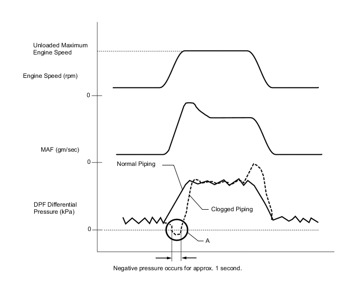
Tech Tips
If DPF Differential Pressure indicates negative pressure for approx. 1 second as shown in the illustration (A) when the engine speed increases, the differential pressure sensor piping of the DPF catalyst may be clogged.
A
GO TO STEP 25 Click here
B
-
-
CHECK BLOCKAGE OF AIR HOSE AND VACUUM PIPE (DIFFERENTIAL PRESSURE SENSOR - VACUUM PIPE)
CAUTION:
Be careful of being burned by exhaust gases during the following inspection.
Tech Tips
Before checking the differential pressure sensor, perform a visual inspection of the differential pressure pipes and check that they are properly connected and no air is leaking from the pipes or hoses. If a malfunction is found, repair it before checking the sensor.
-
*1 Air Hose Disconnect the air hoses (both upstream and downstream) from the differential pressure sensor.
-
Start the engine.
-
Check if there are exhaust gas pulsations from both air hoses during idling.
OK Exhaust gas pulsation exists. Result Proceed to OK NG
NG
REPAIR OR REPLACE NO. 1 VACUUM PIPE OR NO. 2 VACUUM PIPE Click here
OK
-
-
REPLACE DIFFERENTIAL PRESSURE SENSOR
-
Replace the differential pressure sensor.
Result Proceed to NEXT
NEXT
-
-
CHECK FOR BLACK SMOKE
-
Start the engine and drive the vehicle until the engine coolant temperature reaches 75°C (167°F) or higher.
-
Stop the vehicle and allow the engine to idle.
-
Fully depress the accelerator pedal for 5 seconds, and then release it [A].
-
Repeat the procedure [A] 10 times [B].
-
Check for black smoke emission during the procedures [A] and [B].
OK Black smoke is emitted less than 5 times. Tech Tips
Even if the black smoke is very thin, count the number of black smoke emissions if there is any visible smoke.
Result Proceed to OK NG
NG
REPLACE EXHAUST MANIFOLD CONVERTER SUB-ASSEMBLY Click here
OK
-
-
READ VALUE USING GTS (CATALYST DIFFERENTIAL PRESS)
-
Connect the GTS to the DLC3.
-
Start the engine and turn the GTS on.
-
Enter the following menus: Powertrain / Engine / Data List / Diesel Exhaust / Catalyst Differential Press.
-
Check the value of Catalyst Differential Press at 4000 rpm without load.
Powertrain > Engine > Data ListTester Display Catalyst Differential Press Result Result Proceed to Catalyst Differential Press is more than 0.45 A Except above B
A
GO TO STEP 30 Click here
B
PERFORM PM FORCED REGENERATION Click here
-
-
REPAIR OR REPLACE NO. 1 VACUUM PIPE OR NO. 2 VACUUM PIPE
-
Repair or replace No. 1 vacuum pipe or No. 2 vacuum pipe.
Result Proceed to NEXT
NEXT
-
-
READ VALUE USING GTS (DPF DIFFERENTIAL PRESSURE)
-
Connect the GTS to the DLC3.
-
Start the engine and turn the GTS on.
-
Enter the following menus: Powertrain / Engine / Data List / Diesel Exhaust / DPF Differential Pressure.
-
Check the DPF Differential Pressure values from idle speed to unloaded maximum engine speed.
Powertrain > Engine > Data ListTester Display DPF Differential Pressure
Tech Tips
If DPF Differential Pressure indicates negative pressure for approx. 1 second as shown in the illustration (A) when the engine speed increases, the differential pressure sensor piping of the DPF catalyst may be clogged.
OK DPF Differential Pressure increases as engine speed increases from idle speed. Result Proceed to OK NG
NG
GO TO STEP 24 Click here
OK
GO TO STEP 25 Click here
-
-
PERFORM PM FORCED REGENERATION
-
Remove the EFI-B fuse or disconnect the cable from the battery terminal for 60 seconds or more, and then reinstall the EFI-B fuse or reconnect the cable to the battery terminal.
Tech Tips
-
The amount of built up particulate matter recorded by the ECM cannot be initialized by the GTS.
-
If the amount of built up particulate matter recorded by the ECM is not initialized, PM forced regeneration cannot be performed using the GTS.
-
-
Connect the GTS to the DLC3.
-
Turn the ignition switch to ON and turn the GTS on.
-
Clear the DTCs.
Powertrain > Engine > Clear DTCs -
Warm up the engine (engine coolant temperature is 75°C (167°F) or higher).
-
Perform PM forced regeneration.
Result PM forced regeneration completes normally. Result Proceed to OK NG
OK
END
NG
GO TO STEP 16 Click here
-
-
REPLACE EXHAUST MANIFOLD CONVERTER SUB-ASSEMBLY
-
Even though it has been determined that the exhaust manifold converter sub-assembly needs to be replaced, make sure to perform all diagnostic procedures for DTC P244B before replacing it.
Result Proceed to NEXT
NEXT
GO TO STEP 16 Click here
-