ECD SYSTEM(w/ DPF), Diagnostic DTC:P0405, P0406
| DTC Code | DTC Name |
|---|---|
| P0405 | Exhaust Gas Recirculation Sensor "A" Circuit Low |
| P0406 | Exhaust Gas Recirculation Sensor "A" Circuit High |
DESCRIPTION
The EGR valve position sensor is mounted on the electric EGR control valve assembly and used for detecting the EGR valve angle. The EGR valve angle detected by the sensor is sent to the ECM as feedback. The ECM then regulates the EGR valve angle in accordance with engine running conditions.
| DTC No. | Detection Item | DTC Detection Condition | Trouble Area | MIL | Memory |
|---|---|---|---|---|---|
| P0405 | Exhaust Gas Recirculation Sensor "A" Circuit Low | EGR valve position sensor output voltage is less than 0.2 V for 2 seconds. (1 trip detection logic) |
|
Comes on | DTC stored |
| P0406 | Exhaust Gas Recirculation Sensor "A" Circuit High | EGR valve position sensor output voltage is higher than 4.8 V for 2 seconds. (1 trip detection logic) |
|
Comes on | DTC stored |
CONFIRMATION DRIVING PATTERN
| DTC No. | DTC Detection Drive Pattern |
|---|---|
| P0405 | Ignition switch ON for 2 seconds or more |
| P0406 |
MONITOR DESCRIPTION
When the output voltage of the EGR valve position sensor deviates from the normal operating range of 0.2 to 4.8 V for more than 2 seconds, the ECM interprets this as a malfunction of the sensor circuit and illuminates the MIL.
CAUTION / NOTICE / HINT
Note
After replacing the ECM, the new ECM needs registration (Click here ) and initialization Click here.
Tech Tips
Read freeze frame data using the GTS. Freeze frame data records the engine condition when malfunctions are detected. When troubleshooting, freeze frame data can help determine if the vehicle was moving or stationary, if the engine was warmed up or not, and other data from the time the malfunction occurred.
PROCEDURE
-
CHECK ECM (EGR VALVE POSITION SENSOR VOLTAGE)
-
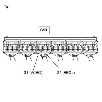
*a Component with harness connected
(ECM)
Measure the voltage according to the value(s) in the table below.
Standard Voltage Tester Connection Switch Condition Specified Condition C59-31 (VCEG) - C59-24 (EEGL) Ignition switch ON 4.5 to 5.5 V Result Proceed to OK NG
NG 
REPLACE ECM Click here
OK 
-
-
INSPECT EGR VALVE POSITION SENSOR (EGLS VOLTAGE)
-
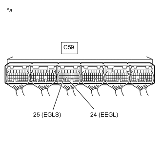
*a Component with harness connected
(ECM)
Measure the voltage according to the value(s) in the table below.
Standard Voltage Tester Connection Switch Condition Specified Condition C59-25 (EGLS) - C59-24 (EEGL) Ignition switch ON 0.6 to 1.4 V Result Proceed to OK NG
NG
CHECK HARNESS AND CONNECTOR Click here
OK
-
-
CONFIRM WHETHER MALFUNCTION HAS BEEN SUCCESSFULLY REPAIRED
-
Connect the GTS to the DLC3.
-
Clear the DTCs.
Powertrain > Engine and ECT > Clear DTCs -
Turn the ignition switch off.
-
Turn the ignition switch to ON for 2 seconds or more.
-
Enter the following menus: Powertrain / Engine and ECT / Trouble Codes.
-
Confirm that the DTC is not output again.
Powertrain > Engine and ECT > Trouble CodesResult Proceed to NEXT
NEXT 
CHECK FOR INTERMITTENT PROBLEMS Click here
-
-
CHECK HARNESS AND CONNECTOR
-
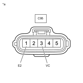
*a Front view of wire harness connector
(to Electric EGR Control Valve Assembly)
Disconnect the electric EGR control valve assembly connector.
-
Measure the voltage according to the value(s) in the table below.
Standard Voltage Tester Connection Switch Condition Specified Condition C95-3 (VC) - C95-1 (E2) Ignition switch ON 4.5 to 5.5 V -
Reconnect the electric EGR control valve assembly connector.
Result Proceed to OK NG
NG
GO TO STEP 8 Click here
OK
-
-
CHECK HARNESS AND CONNECTOR (EGR VALVE POSITION SENSOR - ECM)
-
Disconnect the electric EGR control valve assembly connector.
-
Disconnect the ECM connector.
-
Measure the resistance according to the value(s) in the table below.
Standard Resistance Tester Connection Condition Specified Condition C95-3 (VC) - C59-31 (VCEG) Always Below 1 Ω C95-2 (VTA) - C59-25 (EGLS) Always Below 1 Ω C95-1 (E2) - C59-24 (EEGL) Always Below 1 Ω C95-3 (VC) or C59-31 (VCEG) - Body ground and other terminals Always 10 kΩ or higher C95-2 (VTA) or C59-25 (EGLS) - Body ground and other terminals Always 10 kΩ or higher -
Reconnect the electric EGR control valve assembly connector.
-
Reconnect the ECM connector.
Result Proceed to OK NG
NG
REPAIR OR REPLACE HARNESS OR CONNECTOR Click here
OK
-
-
CHECK ECM (CHECK RESISTANCE)
-
Disconnect the electric EGR control valve assembly connector.
-
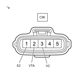
*a Front view of wire harness connector
(to Electric EGR Control Valve Assembly)
Measure the resistance according to the value(s) in the table below.
Standard Resistance Tester Connection Switch Condition Specified Condition C95-3 (VC) - C95-2 (VTA) Ignition switch off No short or open circuit C95-2 (VTA) - C95-1 (E2) -
Reconnect the electric EGR control valve assembly connector.
Result Proceed to OK NG
NG
GO TO STEP 10 Click here
OK
-
-
REPLACE ELECTRIC EGR CONTROL VALVE ASSEMBLY
-
Replace the electric EGR control valve assembly.
Result Proceed to NEXT
NEXT
GO TO STEP 9 Click here
-
-
REPAIR OR REPLACE HARNESS OR CONNECTOR
-
Repair or replace the harness or connector.
Result Proceed to NEXT
NEXT
-
-
CONFIRM WHETHER MALFUNCTION HAS BEEN SUCCESSFULLY REPAIRED
-
Connect the GTS to the DLC3.
-
Clear the DTCs.
Powertrain > Engine and ECT > Clear DTCs -
Turn the ignition switch to ON for 2 seconds or more.
-
Enter the following menus: Powertrain / Engine and ECT / Trouble Codes.
-
Confirm that the DTC is not output again.
Powertrain > Engine and ECT > Trouble CodesResult Proceed to NEXT
NEXT
END
-
-
REPLACE ECM
-
Replace the ECM.
Result Proceed to NEXT
NEXT
GO TO STEP 9 Click here
-