ECD SYSTEM(w/ DPF) PRECAUTION
-
INITIALIZATION AND REGISTRATION
Note
When replacing the ECM and/or any other components in the following chart, perform the corresponding utility items.
Tech Tips
When the ECM and one or more other components are replaced at the same time, perform the following utility items by following the instructions shown on the GTS display, starting with the ECM.
Replacement Part Utility Item ECM
-
Learning Values Save
-
Learning Values Write
-
VIN Registration
Engine assembly
-
Clear Crank Time Compensation Data
-
Input Injector Compensation Code
-
Pilot Quantity Learning
Crankshaft angle sensor plate Clear Crank Time Compensation Data
Air fuel ratio sensor Clear A/F Sensor Compensation data
Exhaust manifold converter sub-assembly Clear DPF Thermal Deterioration Data
Injector assembly
-
Input Injector Compensation Code
-
Pilot Quantity Learning
Diesel throttle body assembly Initialization
Electric EGR control valve assembly Turbocharger sub-assembly or Turbocharger nozzle vane control actuator Tech Tips
When the ECM must be replaced, before replacing the ECM, perform the "Learning Values Save" function using the GTS. Then after installing the new ECM, perform all of the initializations/registrations for the "Learning Values Write" function by following the instructions shown on the GTS display.
-
-
CATALYST RECORD OF DPF THERMAL DETERIORATION
Tech Tips
The ECM stores the history data of DPF catalyst thermal deterioration. This data is updated continuously and is then converted to an 8-digit code and is stored in the EEPROM. If the ECM determines that replacement of the exhaust manifold converter sub-assembly is required based on the thermal deterioration data, the DTC is stored to inform the driver.
-
When only the exhaust manifold converter sub-assembly is replaced.
-
After replacing the exhaust manifold converter sub-assembly, clear the thermal deterioration data stored in the ECM.
-
-
When only the ECM is replaced.
-
After replacing the ECM, input the original thermal deterioration data stored before replacement.
Tech Tips
-
Read the thermal deterioration data stored in the ECM before replacement, and store the data in the GTS.
-
If the thermal deterioration data cannot be read, be sure to replace the exhaust manifold converter sub-assembly with a new one and initialize the ECM.
-
-
-
-
INJECTOR COMPENSATION CODE
Tech Tips
-
Each injector assembly has different fuel injection characteristics. In order to optimize fuel injection performance, the ECM compensates for these differences by adjusting the fuel injection duration of each injector assembly according to its compensation code. Injector compensation codes are unique, 30-digit, alphanumeric values printed on the head portion of each injector assembly.
-
If an incorrect injector compensation code is input into the ECM, the engine may rattle or engine idling may become rough. In addition, engine failure may occur and the life of the engine may be shortened.
-
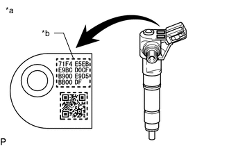
*a Example *b Injector Compensation Code When an injector assembly is replaced, the injector compensation code must be input into the ECM.
-
When the ECM is replaced, all of the existing injector compensation codes must be input into the new ECM.
-
-
PILOT QUANTITY LEARNING
Tech Tips
-
By performing "Pilot Quantity Learning", the injection volume for each cylinder is precisely adjusted so that the engine runs smoothly. The "Pilot Quantity Learning" information is stored in the EEPROM of the ECM.
-
If an incorrect pilot quantity learning value is input into the ECM, the engine may rattle or engine idling may become rough.
-
When an injector assembly is replaced, the injector compensation code must be input to the ECM, and then pilot quantity learning must be performed.
-
When the ECM is replaced, all of the existing injector pilot quantity learning values must be input into the new ECM.
-
-
WHEN USING GTS
CAUTION:
-
Observe the following items for safety reasons:
-
Before using the GTS, read the instruction manual.
-
Prevent the GTS cable from being caught on the pedals, shift lever or steering wheel when driving with the GTS connected to the vehicle.
-
When driving the vehicle for testing purposes using the GTS, 2 persons are required. One drives the vehicle, and the other operates the GTS.
-
-
IGNITION SWITCH EXPRESSIONS
Tech Tips
The type of ignition switch used on this model differs depending on the specifications of the vehicle.
The expressions listed in the table below are used in this section.
Expression Ignition Switch (Position) Engine Switch (Condition) Ignition Switch off LOCK Off (Lock) Ignition Switch ACC ACC On (ACC) Ignition Switch ON ON On (IG) Engine Start START On (Start)