| DTC Code | DTC Name |
|---|---|
| Starter Signal Circuit |
DESCRIPTION
While the engine is being cranked, the starter signal is also sent to terminal STA of the ECM. The starter signal mainly performs engine control when the engine is started.
CAUTION / NOTICE / HINT
-
Inspect the fuses for circuits related to this system before performing the following procedure.
-
After replacing the ECM, the new ECM needs registration (Click here ) and initialization (Click here).
This procedure is based on the premise that the engine can crank normally. If the engine cannot crank normally, proceed to the problem symptoms table.
PROCEDURE
- Click here
READ VALUE USING GTS (STARTER SIGNAL)
-
Connect the GTS to DLC3.
-
Turn the ignition switch to ON.
-
Turn the GTS on.
-
Enter the following menus: Powertrain / Engine and ECT / Data List / Primary / Starter Signal.
- Powertrain > Engine and ECT > Data List
Tester Display Starter Signal -
-
-
-
- Powertrain > Engine and ECT > Data List
-
Check the value displayed on the GTS when the ignition switch is turned to the ON and START positions.
OK Ignition Switch Position Starter Signal ON OFF START ON Result Proceed to OK NG
- OK
PROCEED TO NEXT SUSPECTED AREA SHOWN IN PROBLEM SYMPTOMS TABLEClick here
- NGClick here
-
- Click here
INSPECT ST NO. 1 RELAY (POWER SOURCE)
-
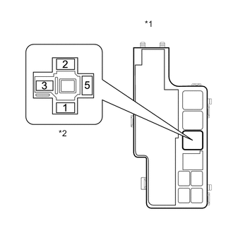
*1 Engine Room Relay Block and Junction Block *2 ST NO. 1 Relay Remove the ST NO. 1 relay from the engine room relay block and junction block.
-
Measure the voltage according to the value(s) in the table below.
Standard Voltage Tester Connection Condition Specified Condition ST NO. 1 relay terminal 2 - Body ground Engine cranking 11 to 14 V Tip:The engine does not crank because the relay is not installed.
Result Proceed to OK NG (for Manual transmission) NG (for Automatic transmission)
- OKClick here
- NG (for Automatic transmission)Click here
- NG (for Manual transmission)Click here
-
- Click here
INSPECT ST NO. 1 RELAY
-
Inspect the ST NO. 1 relay.
Result Proceed to OK NG
- OKClick here
- NG
REPLACE ST NO. 1 RELAY
-
- Click here
CHECK HARNESS AND CONNECTOR (ENGINE ROOM RELAY BLOCK AND JUNCTION BLOCK - BODY GROUND)
-
Remove the ST NO. 1 relay from the engine room relay block and Junction block.
-
Measure the resistance according to the value(s) in the table below.
Standard Resistance Tester Connection Condition Specified Condition ST NO. 1 relay terminal 1 - Body ground Always Below 1 Ω Result Result OK NG
- OK
REPAIR OR REPLACE HARNESS OR CONNECTOR (ECM - PARK/NEUTRAL POSITION SWITCH ASSEMBLY OR CLUTCH START SWITCH)
- NG
REPAIR OR REPLACE HARNESS OR CONNECTOR (ST NO. 1 RELAY - BODY GROUND)
-
- Click here
CHECK HARNESS AND CONNECTOR (PARK/NEUTRAL POSITION SWITCH ASSEMBLY - ST NO. 1 RELAY)
-
Remove the ST NO. 1 relay from the engine room relay block and junction block.
-
Disconnect the park/neutral position switch assembly connector.
-
Measure the resistance according to the value(s) in the table below.
Standard Resistance Tester Connection Condition Specified Condition C22-5 - ST NO. 1 relay terminal 2 Always Below 1 Ω G85-22 (STA) - ST NO. 1 relay terminal 2 Always Below 1 Ω Result Proceed to OK NG
- OKClick here
- NG
REPAIR OR REPLACE HARNESS OR CONNECTOR
-
- Click here
INSPECT PARK/NEUTRAL POSITION SWITCH ASSEMBLY
-
Inspect the park/neutral position switch assembly.
-
for AC60E
-
for AC60F
Result Result OK NG -
- OKClick here
- NG
REPLACE PARK/NEUTRAL POSITION SWITCH ASSEMBLY
for AC60E
for AC60F
-
- Click here
CHECK HARNESS AND CONNECTOR (IGNITION SWITCH ASSEMBLY - PARK/NEUTRAL POSITION SWITCH ASSEMBLY - ECM)
-
Disconnect the ignition switch assembly connector.
-
Disconnect the park/neutral position switch assembly connector.
-
Disconnect the ECM connector.
-
Measure the resistance according to the value(s) in the table below.
Standard Resistance Tester Connection Condition Specified Condition G1-2 (ST2) - C22-4 Always Below 1 Ω G1-2 (ST2) - G85-11 (NSW) Always Below 1 Ω G1-2 (ST2) or C22-4 or G85-11 (NSW) - Body ground and other terminals Always 10 kΩ or higher Result Proceed to OK NG
- OKClick here
- NG
REPAIR OR REPLACE HARNESS OR CONNECTOR
-
- Click here
INSPECT IGNITION SWITCH ASSEMBLY
-
Inspect the ignition switch assembly.
Result Proceed to OK NG
- OK
REPAIR OR REPLACE HARNESS OR CONNECTOR (BATTERY - IGNITION SWITCH ASSEMBLY)
- NG
REPLACE IGNITION SWITCH ASSEMBLYClick here
-
- Click here
CHECK HARNESS AND CONNECTOR (CLUTCH START SWITCH - ST NO. 1 RELAY)
-
Remove the ST NO. 1 relay from the engine room relay block and junction block.
-
Disconnect the clutch start switch connector.
-
Measure the resistance according to the value(s) in the table below.
Standard Resistance Tester Connection Condition Specified Condition B2-1 - ST NO. 1 relay terminal 2 Always Below 1 Ω G85-22 (STA) - ST NO. 1 relay terminal 2 Always Below 1 Ω Result Proceed to OK NG
- OKClick here
- NG
REPAIR OR REPLACE HARNESS OR CONNECTOR
-
- Click here
INSPECT CLUTCH START SWITCH
-
Inspect the clutch start switch.
Result Result OK NG
- OKClick here
- NG
REPLACE CLUTCH START SWITCHClick here
-
- Click here
CHECK HARNESS AND CONNECTOR (IGNITION SWITCH ASSEMBLY - CLUTCH START SWITCH - ECM)
-
Disconnect the ignition switch assembly connector.
-
Disconnect the clutch start switch connector.
-
Disconnect the ECM connector.
-
Measure the resistance according to the value(s) in the table below.
Standard Resistance Tester Connection Condition Specified Condition G1-2 (ST2) - B2-2 Always Below 1 Ω G1-2 (ST2) - G85-11 (NSW) Always Below 1 Ω G1-2 (ST2) or B2-2 or G85-11 (NSW) - Body ground and other terminals Always 10 kΩ or higher Result Proceed to OK NG
- OKClick here
- NG
REPAIR OR REPLACE HARNESS OR CONNECTOR
-
- Click here
INSPECT IGNITION SWITCH ASSEMBLY
-
Inspect the ignition switch assembly.
Result Proceed to OK NG
- OK
REPAIR OR REPLACE HARNESS OR CONNECTOR (BATTERY - IGNITION SWITCH ASSEMBLY)
- NG
REPLACE IGNITION SWITCH ASSEMBLYClick here
-