ECD SYSTEM(w/ DPF) Intake/Exhaust System
CAUTION / NOTICE / HINT
Note
After replacing the ECM, the new ECM needs registration (Click here) and initialization Click here.
PROCEDURE
-
TAKE SNAPSHOT DURING IDLING AND 4000 RPM (PROCEDURE 1)
-
Connect the GTS to the DLC3.
-
Start the engine and turn the GTS on.
-
Enter the following menus: Powertrain / Engine and ECT / Data List / Primary.
-
Take a snapshot of the Data List items.
Tech Tips
-
A snapshot can be used to compare vehicle data from the time of the malfunction to normal data and is very useful for troubleshooting.
-
Check the Data List at idling and at 4000 rpm with no load after the engine is warmed up.
Result Proceed to NEXT -
NEXT 
-
-
READ VALUE USING GTS (MAP AND MAF)
-
Check MAP and MAF in the snapshot taken in procedure 1 when the engine was running at 4000 rpm with no load.
Result Result Proceed to MAP is below 90 kPa*1 A MAP is 140 kPa or higher and MAF is 85 gm/sec or more*2 B Except above*3 C Tech Tips
The above values were measured under standard atmospheric pressure. The value are influenced by elevation, weather conditions, etc.
Standard atmospheric pressure is 101 kPa (1.0 kgf/cm2, 15 psi). For every 100 m (328 ft.) increase in elevation, pressure drops by 1 kPa (0.01 kgf/cm2, 0.1 psi). This varies by weather.
*1: There may be a problem in the turbocharger system.
*2: There may be a problem in the fuel system or intake system.
*3: There may be a problem in intake system or a problem with the EGR valve (valve stuck open or valve does not close).
B 
GO TO STEP 19 Click here
C
CHECK INTAKE SYSTEM Click here
A
-
-
READ VALUE USING GTS (MAP AND ATMOSPHERE PRESSURE)
-
Connect the GTS to the DLC3.
-
Start the engine and turn the GTS on.
-
Enter the following menus: Powertrain / Engine and ECT / Data List / All Data / MAP and Atmosphere Pressure.
Powertrain > Engine > Data ListTester Display Atmosphere Pressure MAP -
Compare MAP and Atmosphere Pressure when the ignition switch ON (do not start the engine).
Standard Difference between MAP and Atmosphere Pressure is less than 8 kPa. Tech Tips
-
If MAP and Atmosphere Pressure have the same value, both are normal. If there is a difference of 10 kPa or higher, compare the values to the atmospheric pressure for that day. The sensor whose deviation is the greatest is malfunctioning.
-
Standard atmospheric pressure is 101 kPa (1.0 kgf/cm2, 15 psi). For every 100 m (328 ft.) increase in elevation, pressure drops by 1 kPa (0.01 kgf/cm2, 0.1 psi). This varies by weather.
Result Result Proceed to MAP and Atmosphere Pressure have same value A MAP is different from actual atmospheric pressure B Atmosphere Pressure is different from actual atmospheric pressure C -
B
REPLACE MANIFOLD ABSOLUTE PRESSURE SENSOR Click here
C
REPLACE ECM Click here
A
-
-
CHECK INTAKE SYSTEM
-
Check for air leaks and blockages between the air cleaner case sub-assembly and turbocharger sub-assembly, and between the turbocharger sub-assembly and intake manifold.
Result Result Proceed to No leaks or blockages in the intake system A Leaks and/or blockages exist in the intake system B Tech Tips
-
Inspect the intake system, especially hoses and pipes between the air cleaner case sub-assembly and turbocharger sub-assembly.
-
Check for abnormal disconnections, pipe and hose squashing, and any damage in the intake system.
-
Using your hand, check whether the pipes and hoses in the intake system are securely connected.
-
By applying soapy water and revving up the engine, air leaks from the intake system can be checked by checking for bubbles.
-
Make sure that the hose between the manifold absolute pressure sensor and intake manifold is not loose or disconnected.
-
Check for any modifications in the intake system made by the user.
-
B
REPAIR OR REPLACE INTAKE SYSTEM Click here
A
-
-
INSPECT TURBOCHARGER SUB-ASSEMBLY
-
Inspect the turbocharger sub-assembly.
Result Proceed to OK NG
NG
REPLACE TURBOCHARGER SUB-ASSEMBLY Click here
OK
-
-
CHECK FOR INTERMITTENT PROBLEMS
-
Check for intermittent problems.
Result Proceed to NEXT
NEXT
GO TO STEP 19 Click here
-
-
REPLACE TURBOCHARGER SUB-ASSEMBLY
-
Replace the turbocharger sub-assembly.
Result Proceed to NEXT
NEXT
GO TO STEP 19 Click here
-
-
REPAIR OR REPLACE INTAKE SYSTEM
-
Repair or replace the malfunctioning part in the intake system.
Result Proceed to NEXT
NEXT
GO TO STEP 19 Click here
-
-
REPLACE MANIFOLD ABSOLUTE PRESSURE SENSOR
-
Replace the manifold absolute pressure sensor.
Result Proceed to NEXT
NEXT
GO TO STEP 19 Click here
-
-
REPLACE ECM
-
Replace the ECM.
Result Proceed to NEXT
NEXT
GO TO STEP 19 Click here
-
-
CHECK INTAKE SYSTEM
-
Check for air leaks and blockages between the air cleaner case sub-assembly and turbocharger sub-assembly, and between the turbocharger sub-assembly and intake manifold.
Result Result Proceed to No leaks or blockages in the intake system A Leaks and/or blockages exist in the intake system B Tech Tips
-
Inspect the intake system, especially hoses and pipes between the air cleaner case sub-assembly and turbocharger sub-assembly.
-
Check for abnormal disconnections, pipe and hose squashing, and any damage in the intake system.
-
Using your hand, check whether the pipes and hoses in the intake system are securely connected.
-
By applying soapy water and revving up the engine, air leaks from the intake system can be checked by checking for bubbles.
-
Make sure that the hose between the manifold absolute pressure sensor and intake manifold is not loose or disconnected.
-
Check for any modifications in the intake system made by the user.
-
B
REPAIR OR REPLACE INTAKE SYSTEM Click here
A
-
-
PERFORM ACTIVE TEST USING GTS (ACTIVATE THE EGR VALVE CLOSE)
-
Connect the GTS to the DLC3.
-
Start the engine and warm it up, and make sure the A/C switch and all accessory switches are off.
-
Turn the ignition switch off and wait for 30 seconds.
-
Start the engine and turn the GTS on.
-
Enter the following menus: Powertrain / Engine and ECT / Data List / Primary / MAF.
Powertrain > Engine > Data ListTester Display MAF -
Read the MAF value displayed on the GTS while the engine is idling.
-
Enter the following menus: Powertrain / Engine and ECT / Active Test / Activate the EGR Valve Close / All Data / MAF.
Powertrain > Engine > Active TestActive Test Display Activate the EGR Valve Close Data List Display MAF -
Read the MAF value when the EGR valve is closed using the Active Test function.
Tech Tips
-
If idling continues for 20 minutes or more, the EGR valve target opening angle becomes 0% (EGR valve fully closed). As this makes diagnosis impossible, it becomes necessary to drive the vehicle or to restart the engine.
-
Before performing the diagnosis, confirm that the EGR valve target opening angle is not 0%.
-
When idling the engine, the EGR cooler sub-assembly is bypassed.
Result GTS Display Result Proceed to Activate the EGR Valve Close:
OFF (Open) to Close
MAF value changes A MAF value does not change B Note
As the measured values may differ from those shown below due to factors such as differences in measuring environments and changes in vehicle condition due to aging, do not use these values to determine whether the vehicle is malfunctioning or not.
Tech Tips
The problem may be a temporary, due to the entry of deposits or foreign matter. Check that there are no deposits or foreign matter in the electric EGR control valve assembly or mass air flow meter assembly.
Reference EGR Valve Condition (Opening) Measuring Condition MAF (Reference) Open (55%)
-
Atmosphere pressure: 101 kPa
-
Engine coolant temperature: 75°C (167°F)
3 to 7 gm/sec Closed (0%) 11 to 16 gm/sec -
B
READ VALUE USING GTS (MAF) Click here
A
-
-
PERFORM ACTIVE TEST USING GTS (ACTIVATE THE VSV FOR EGR COOLER BYPASS)
-
Connect the GTS to the DLC3.
-
Start the engine and warm it up, and make sure the A/C switch and all accessory switches are off.
-
Turn the ignition switch off and wait for 30 seconds.
-
Start the engine and turn the GTS on.
-
Enter the following menus: Powertrain / Engine and ECT / Data List / Primary / MAF.
Powertrain > Engine > Data ListTester Display MAF -
Read the MAF value displayed on the GTS while the engine is idling.
-
Enter the following menus: Powertrain / Engine and ECT / Active Test / Activate the VSV for EGR Cooler Bypass / All Data / EGR Cooler Bypass Position and MAF.
Tech Tips
Whether the EGR is passing through the bypass side or cooler side during the Active Test can be confirmed by checking EGR Cooler Bypass Position.
Powertrain > Engine > Active TestActive Test Display Activate the VSV for EGR Cooler Bypass Data List Display MAF EGR Cooler Bypass Position -
Using the Active Test function, switch the EGR valve bypass switching valve between "Cooler" and "Bypass" a few times, and then check whether the MAF value changes after switching the valve from "Cooler" to "Bypass".
Tech Tips
-
Using the Active Test function, switch the EGR valve bypass switching valve between "Cooler" and "Bypass" a few times, and then check whether the MAF value changes after switching the valve from "Cooler" to "Bypass".
-
When operating "Activate the VSV for EGR Cooler Bypass", check that "Cooler" and "Bypass" can be switched between and the EGR cooler by-pass valve regulating link operates. If the link does not operate, the inspection cannot be performed correctly. Therefore, inspect and repair the following parts, perform the Active Test and read the changes in the MAF value.
-
No. 2 EGR valve assembly
-
Vacuum hose connection
-
Vacuum switching valve assembly (for EGR bypass valve)
Result GTS Display Result Proceed to Activate the VSV for EGR Cooler Bypass:
Cooler to Bypass
MAF value does not change A MAF value changes B Tech Tips
If the EGR pipe with cooler sub-assembly is clogged, the MAF value changes.
-
A
GO TO STEP 19 Click here
B
GO TO STEP 17 Click here
-
-
READ VALUE USING GTS (MAF)
-
Connect the GTS to the DLC3.
-
Turn the ignition switch to ON and turn the GTS on.
-
Enter the following menus: Powertrain / Engine and ECT / Data List / MAF and Engine speed.
Powertrain > Engine > Data ListTester Display Engine Speed MAF -
Read the value.
Standard Engine Speed MAF Idling 3 to 18 gm/sec 3000 rpm 45 to 94 gm/sec Result Proceed to OK NG
NG
REPLACE MASS AIR FLOW METER SUB-ASSEMBLY Click here
OK
-
-
PERFORM ACTIVE TEST USING GTS (ACTIVATE THE VSV FOR EGR COOLER BYPASS)
-
Connect the GTS to the DLC3.
-
Start the engine and warm it up, and make sure the A/C switch and all accessory switches are off.
-
Turn the ignition switch off and wait for 30 seconds.
-
Start the engine and turn the GTS on.
-
Enter the following menus: Powertrain / Engine and ECT / Data List / Primary / MAF.
Powertrain > Engine > Data ListTester Display MAF -
Read the MAF value displayed on the GTS while the engine is idling.
-
Enter the following menus: Powertrain / Engine and ECT / Active Test / Activate the VSV for EGR Cooler Bypass / All Data / EGR Cooler Bypass Position and MAF.
Tech Tips
Whether the EGR is passing through the bypass side or cooler side during the Active Test can be confirmed by checking EGR Cooler Bypass Position.
Powertrain > Engine > Active TestActive Test Display Activate the VSV for EGR Cooler Bypass Data List Display MAF EGR Cooler Bypass Position -
Using the Active Test function, switch the EGR valve bypass switching valve between "Cooler" and "Bypass" a few times, and then check whether the MAF value changes after switching the valve from "Cooler" to "Bypass".
Tech Tips
-
Using the Active Test function, switch the EGR valve bypass switching valve between "Cooler" and "Bypass" a few times, and then check whether the MAF value changes after switching the valve from "Cooler" to "Bypass".
-
When operating "Activate the VSV for EGR Cooler Bypass", check that "Cooler" and "Bypass" can be switched between and the EGR cooler by-pass valve regulating link operates. If the link does not operate, the inspection cannot be performed correctly. Therefore, inspect and repair the following parts, perform the Active Test and read the changes in the MAF value.
-
No. 2 EGR valve assembly
-
Vacuum hose connection
-
Vacuum switching valve assembly (for EGR bypass valve)
Result GTS Display Result Proceed to Activate the VSV for EGR Cooler Bypass:
Cooler to Bypass
MAF value does not change A MAF value changes B Tech Tips
If the EGR pipe with cooler sub-assembly is clogged, the MAF value changes.
-
B
GO TO STEP 17 Click here
A
-
-
CHECK FOR DEPOSIT (ELECTRIC EGR CONTROL VALVE ASSEMBLY)
-
Remove the electric EGR control valve assembly.
-
Visually check the electric EGR control valve assembly for deposits. If there are deposits, clean the electric EGR control valve assembly.
Note
-
When cleaning the electric EGR control valve assembly, make sure the valve is completely closed.
-
When cleaning the electric EGR control valve assembly, perform initialization procedure.
-
Do not forcibly open the valve, as it may be damaged or deformed.
-
When cleaning the electric EGR control valve assembly, use a piece of cloth soaked with cleaning solvent. Spraying solvent directly onto these parts or soaking the parts in solvent may damage the parts.
-
When cleaning the electric EGR control valve assembly, care should be taken to prevent the ingress of cleaning solvent into the bearings of valve shaft, and when wiping off deposits on the electric EGR control valve assembly, care should be taken not to push the deposits into the bearings of valve shaft. These contaminants may adversely affect on the function of electric EGR control valve assembly.
Tech Tips
-
If the EGR valve does not open properly or is stuck closed, the amount of intake air increases and combustion sounds and engine vibration may increase.
-
If the EGR valve does not close properly or is stuck open, the amount of recirculated exhaust gas becomes excessive and combustion becomes unstable. Also, there may be a lack of power.
Result Proceed to NEXT -
NEXT
-
-
REPLACE EGR COOLER SUB-ASSEMBLY
-
Replace the EGR cooler sub-assembly.
Result Proceed to NEXT
NEXT
GO TO STEP 19 Click here
-
-
REPLACE MASS AIR FLOW METER SUB-ASSEMBLY
-
Replace the mass air flow meter sub-assembly.
Tech Tips
If foreign matter is stuck inside the mass air flow meter sub-assembly, the output characteristics of the mass air flow meter sub-assembly may change, resulting in a malfunction.
Result Proceed to NEXT
NEXT
-
-
CHECK INTAKE MANIFOLD (SWIRL CONTROL VALVE OPERATION)
-
Connect the GTS to the DLC3.
-
Start the engine and turn the GTS on.
-
Warm up the engine (engine coolant temperature is 75°C (167°F) or higher).
-
Enter the following menus: Powertrain / Engine and ECT / Active Test / Activate the VSV for Swirl Control Valve.
Powertrain > Engine > Active TestTester Display Activate the VSV for Swirl Control Valve -
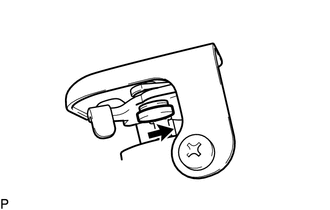
Perform the Active Test.
OK Swirl control valve rod moves smoothly in the direction indicated by the arrow in the illustration. Result Proceed to NEXT
NEXT
-
-
CONFIRM WHETHER MALFUNCTION HAS BEEN SUCCESSFULLY REPAIRED
Result Proceed to NEXT
NEXT 
END
-
REPAIR OR REPLACE INTAKE SYSTEM
-
Repair or replace the malfunctioning part in the intake system.
Result Proceed to NEXT
NEXT
GO TO STEP 19 Click here
-