ECD SYSTEM(w/ DPF), Diagnostic DTC:P2006
| DTC Code | DTC Name |
|---|---|
| P2006 | Intake Manifold Runner Control Stuck Closed (Bank 1) |
DESCRIPTION
The swirl control valve is mounted on the intake manifold. The vacuum switching valve is used to change the vacuum to control the swirl control valve.
The ECM determines the opening angle of the swirl control valve, and uses the vacuum switching valve (for swirl control valve) to change the vacuum applied to the actuator's diaphragm to open and close the swirl control valve.
| DTC No. | Detection Item | DTC Detection Condition | Trouble Area | MIL | Memory |
|---|---|---|---|---|---|
| P2006 | Intake Manifold Runner Control Stuck Closed (Bank 1) | When actual intake air volume detected by mass air flow meter continues to be smaller than volume estimated from boost pressure and intake air temperature sensor, ECM determines that swirl control valve is stuck closed (1 trip detection logic). |
|
Comes on | DTC stored |
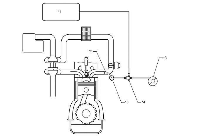
| *1 | ECM | *2 | Swirl Control Valve |
| *3 | Vacuum Pump | *4 | Vacuum Switching Valve (for Swirl Control Valve) |
| *5 | Swirl Control Valve Actuator | - | - |
CONFIRMATION DRIVING PATTERN
| DTC Detection Drive Pattern | After warming up engine, drive vehicle at an engine speed of 3200 rpm or more with high load for 1 minute or more.* |
Tech Tips
*: When the above driving pattern cannot be performed due to road conditions, etc., the swirl control valve can be determined to be functioning normally if mass air flow is 84 gm/s or more and MAP is 105 kPa or higher when the engine speed is at 4000 rpm with no load. However, no DTCs are stored when inspecting the vehicle with this method.
The above values were measured under standard atmospheric pressure. The values are influenced by elevation, weather conditions, etc.
Standard atmospheric pressure is 101 kPa. For every 100 m increase in elevation, pressure drops by 1 kPa. This varies by weather.
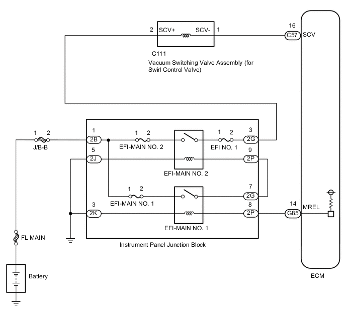
WIRING DIAGRAM
CAUTION / NOTICE / HINT
Note
-
After replacing the ECM, the new ECM needs registration (See page ) and initialization Click here.
Tech Tips
Read freeze frame data using the GTS. Freeze frame data records the engine condition when malfunctions are detected. When troubleshooting, freeze frame data can help determine if the vehicle was moving or stationary, if the engine was warmed up or not, and other data from the time the malfunction occurred.
PROCEDURE
-
CHECK OTHER DTC OUTPUT (IN ADDITION TO DTC P2006)
-
Connect the GTS to the DLC3.
-
Turn the ignition switch to ON and turn the GTS on.
-
Enter the following menus: Powertrain / Engine and ECT / DTC.
Powertrain > Engine > Trouble Codes -
Read the DTCs.
Result Result Proceed to P2006 is output A P2006 and other DTCs are output B Tech Tips
When manifold absolute pressure sensor, mass air flowsub-assembly, intake air temperature sensor, and/orintake air temperature sensor (Turbo) related DTCs arestored along with P2006, perform troubleshooting forthose DTCs first.
Manifold absolute pressure sensor-related DTCs: P0107and P0108.
Mass air flow sub-assembly-related DTCs: P0100.
Intake air temperature sensor-related DTCs: P0112 and P0113.
intake air temperature sensor (Turbo)-related DTCs: P007C and P007D.
B 
GO TO RELEVANT DTC CHART Click here
A 
-
-
CHECK AIR INTAKE SYSTEM
-
Check for air leakage and blockage between the air cleaner cap and turbocharger sub-assembly, and between the turbocharger sub-assembly and intake manifold.
Result Result Proceed to Leaks and/or blockages exist in the intake system A No leaks or blockages in the intake system B Tech Tips
-
Inspect the air intake system, especially hoses and pipes between the air cleaner and turbocharger.
-
Check if the air cleaner element is significantly dirty.
-
Check for abnormal disconnections, pipe and hose squashing, and any damage in the intake system.
-
Using your hand, check whether the pipes and hoses in the intake system are securely connected.
-
By applying soapy water and revving up the engine, air leaks from the intake system can be checked by checking for bubbles.
-
Check for any modifications in the intake system made by the user.
-
B 
CHECK INTAKE MANIFOLD (SWIRL CONTROL VALVE OPERATION) Click here
A
-
-
REPAIR OR REPLACE INTAKE SYSTEM
-
Repair or replace the malfunctioning part in the intake system.
Result Proceed to NEXT
NEXT
-
-
CHECK INTAKE MANIFOLD (SWIRL CONTROL VALVE OPERATION)
-
Connect the GTS to the DLC3.
-
Start the engine and turn the GTS on.
-
Warm up the engine (engine coolant temperature is 75°C (167°F) or higher).
-
Enter the following menus: Powertrain / Engine and ECT / Active Test / Activate the VSV for Swirl Control Valve.
Powertrain > Engine > Active TestTester Display Activate the VSV for Swirl Control Valve -
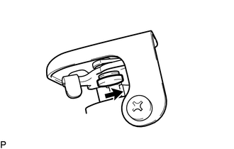
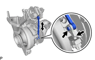
Perform the Active Test.
OK Swirl control valve rod moves smoothly in the direction indicated by the arrow in the illustration. Result Proceed to OK NG
NG
CHECK CONNECTION OF VACUUM HOSE Click here
OK
-
-
READ VALUE USING GTS (MAF AND MAP)
-
Connect the GTS to the DLC3.
-
Start the engine and turn the GTS on.
-
Warm up the engine (engine coolant temperature is 70°C (158°F) or higher).
-
Enter the following menus: Powertrain / Engine and ECT / Data List / MAP and MAF.
Powertrain > Engine > Data ListTester Display MAF MAP -
Take a snapshot when the engine speed is maintained at 4000 rpm with no load.
-
Read the values of "MAP" and "MAF" in the Data List using the snapshot review function.
Result Result Proceed to MAF 84 gm/s or more and MAP 105 kPa or higher C MAP below 90 kPa B Except above A Tech Tips
-
The shift lever should be in neutral and the A/C switch and all accessory switches should be off.
-
The above values were measured under standard atmospheric pressure. The values are influenced by elevation, weather conditions, etc. Standard atmospheric pressure is 101 kPa. For every 100 m increase in elevation, pressure drops by 1 kPa. This varies by weather.
-
B
INSPECT TURBOCHARGER NOZZLE VANE PLATE Click here
C
END
A
-
-
REPLACE MASS AIR FLOW METER SUB-ASSEMBLY
-
Replace the mass air flow meter sub-assembly.
Tech Tips
If foreign matter is stuck inside the mass air flow meter, the output characteristics of the mass air flow meter may change, resulting in a malfunction.
Result Proceed to NEXT
NEXT
GO TO STEP 17 Click here
-
-
CHECK CONNECTION OF VACUUM HOSE
-
Check the connection of the swirl control valve system vacuum hose.
Result Proceed to OK NG
NG
REPAIR OR REPLACE VACUUM HOSE Click here
OK
-
-
PERFORM ACTIVE TEST USING INTELLIGENT TESTER (ACTIVATE THE VSV FOR SWIRL CONTROL VALVE)
-
Disconnect the vacuum hoses from the VSV for swirl control valve.
-
Connect the GTS to the DLC3.
-
Turn the ignition switch to ON and turn the GTS on.
-
Enter the following menus: Powertrain / Engine and ECT / Active Test / Activate the VSV for Swirl Control Valve.
Powertrain > Engine > Active TestTester Display Activate the VSV for Swirl Control Valve -
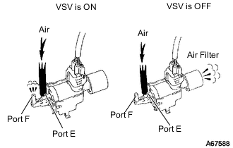
Check the VSV operation when it is operated using the GTS.
OK Tester Operation Specified Condition VSV ON Air from port E flows out through port F VSV OFF Air from port E flows out through air filter -
Reconnect the vacuum hoses.
Result Proceed to OK NG
NG
REPLACE VACUUM CONTROL VALVE SET Click here
OK
-
-
INSPECT ELECTRIC EGR CONTROL VALVE ASSEMBLY
-
Inspect the electric EGR control valve assembly.
Tech Tips
-
If there are any deposits adhering to the valve, clean the valve. When cleaning the valve, use diesel fuel or kerosene.
-
When inspecting the electric EGR control valve assembly, make sure that the valve is fully closed.
Result Proceed to OK NG -
OK
GO TO STEP 15 Click here
NG
REPLACE ELECTRIC EGR CONTROL VALVE ASSEMBLY Click here
-
-
INSPECT TURBOCHARGER NOZZLE VANE PLATE
-
Remove the turbocharger sub-assembly.
-
Inspect the turbocharger nozzle vane plate.
-
Remove the e-washer from the turbocharger nozzle vane control actuator.
-
-
Move the turbocharger vane control rod sub-assembly and check that the turbocharger nozzle vane support plate moves.
Result Result Proceed to Catches, but operates* OK Gets stuck and does not operate NG Tech Tips
*: Check several times.
OK
REPLACE TURBOCHARGER NOZZLE VANE CONTROL ACTUATOR Click here
NG
REPLACE TURBOCHARGER SUB-ASSEMBLY Click here
-
-
REPAIR OR REPLACE VACUUM HOSE
-
Repair or replace the vacuum hose.
Result Proceed to NEXT
NEXT
GO TO STEP 17 Click here
-
-
REPLACE VACUUM CONTROL VALVE SET
-
Replace the vacuum control valve set.
Tech Tips
Before replacing the vacuum control valve set, perform a wire harness inspection and if there are any problems with the wire harness, repair or replace it.
Result Proceed to NEXT
NEXT
-
-
PERFORM ACTIVE TEST USING INTELLIGENT TESTER (ACTIVATE THE VSV FOR SWIRL CONTROL VALVE)
-
Disconnect the vacuum hoses from the vacuum switching valve (for swirl control valve).
-
Connect the GTS to the DLC3.
-
Turn the ignition switch to ON and turn the GTS on.
-
Enter the following menus: Powertrain / Engine and ECT / Active Test / Activate the VSV for Swirl Control Valve.
Powertrain > Engine > Active TestTester Display Activate the VSV for Swirl Control Valve -
Check the VSV operation when it is operated using the GTS.
OK Tester Operation Specified Condition VSV ON Air from port E flows out through port F VSV OFF Air from port E flows out through air filter -
Reconnect the vacuum hoses.
Result Proceed to OK NG
OK
GO TO STEP 17 Click here
NG
REPLACE ECM Click here
-
-
REPLACE ELECTRIC EGR CONTROL VALVE ASSEMBLY
-
Replace the electric EGR control valve assembly.
Result Proceed to NEXT
NEXT
-
-
INSPECT INTAKE MANIFOLD (SWIRL CONTROL VALVE OPERATION)
-
Inspect the intake manifold (swirl control valve).
Tech Tips
-
If there are any deposits adhering to the valve, clean the valve.
-
If there are any deposits adhering to the valve, clean the valve. When cleaning the valve, use diesel fuel or kerosene.
-
Apply vacuum to the diaphragm of the swirl control valve and check that the valve opens and closes smoothly.
Result Proceed to OK NG -
OK
GO TO STEP 17 Click here
NG
REPLACE INTAKE MANIFOLD Click here
-
-
REPLACE ECM
-
Replace the ECM.
Result Proceed to NEXT
NEXT
-
-
CONFIRM WHETHER MALFUNCTION HAS BEEN SUCCESSFULLY REPAIRED
-
Connect the GTS to the DLC3.
-
Start the engine and turn the GTS on.
-
Warm up the engine (engine coolant temperature is 70°C (158°F) or higher).
-
Enter the following menus: Powertrain / Engine and ECT / Data List / MAP and MAF.
-
Take a snapshot when the engine speed is maintained at 4000 rpm with no load.
-
Read the values of "MAP" and "MAF" in the Data List using the snapshot review function.
OK MAF is 84 gm/s or more and MAP is 105 kPa or higher. Tech Tips
-
The shift lever should be in neutral and the A/C switch and all accessory switches should be off.
-
The above values were measured under standard atmospheric pressure. The values are influenced by elevation, weather conditions, etc. Standard atmospheric pressure is 101 kPa. For every 100 m increase in elevation, pressure drops by 1 kPa. This varies by weather.
Result Proceed to NEXT -
NEXT
END
-
-
REPLACE INTAKE MANIFOLD
-
Replace the intake manifold (swirl control valve).
Result Proceed to NEXT
NEXT
GO TO STEP 17 Click here
-