ECD SYSTEM, Diagnostic DTC:P1520
| DTC Code | DTC Name |
|---|---|
| P1520 | Stop Light Switch Circuit Malfunction |
DESCRIPTION
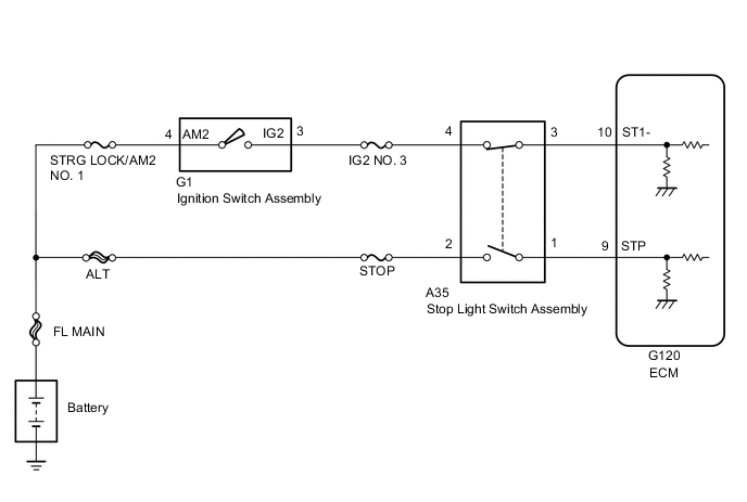
In this system, the signal of the stop light switch is used to judge whether the stop light system is abnormal or not.
The stop light switch has a duplex system (signals STP and ST1-) to recognize the abnormality when the signals of depressing and releasing the brake pedal are detected simultaneously.
Tech Tips
The normal signal conditions are as shown in the table below.
| Signal | Brake Pedal Released | In Transition | Brake Pedal Depressed |
|---|---|---|---|
| STP | OFF | ON | ON |
| ST1- | ON | ON | OFF |
| DTC No. | Detection Item | DTC Detection Condition | Trouble Area | MIL | Memory |
|---|---|---|---|---|---|
| P1520 | Stop Light Switch Circuit Malfunction | Conditions (a), (b) and (c) continue for 0.5 seconds or more (1 trip detection logic): (a) Ignition switch is ON. (b) Brake pedal is released. (c) The STP signal is off when the ST1- signal is off. |
|
- | DTC stored |
WIRING DIAGRAM
CAUTION / NOTICE / HINT
Note
Inspect the fuses for circuits related to this system before performing the following inspection procedure.
Tech Tips
Read freeze frame data using the intelligent tester. Freeze frame data records the engine condition when malfunctions are detected. When troubleshooting, freeze frame data can help determine if the vehicle was moving or stationary, if the engine was warmed up or not, and other data from the time the malfunction occurred.
PROCEDURE
-
CHECK STOP LAMP SWITCH ASSEMBLY (TERMINAL B VOLTAGE)
-
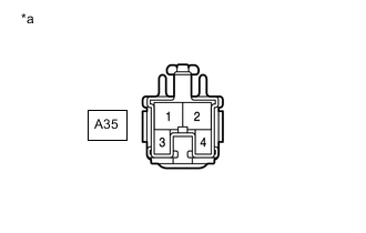
*a Front view of wire harness connector
(to Stop Light Switch)
Disconnect the stop light switch connector.
-
Measure the voltage according to the value(s) in the table below.
Standard Voltage Tester Connection Condition Specified Condition A35-2 - Body ground Always 11 to 14 V A35-4 - Body ground Ignition switch ON 11 to 14 V -
Reconnect the stop light switch connector.
Result Proceed to OK NG
NG 
GO TO STEP 5 Click here
OK 
-
-
INSPECT STOP LIGHT SWITCH ASSEMBLY
-
Inspect the stop light switch assembly.
Result Proceed to OK NG
NG
REPLACE STOP LIGHT SWITCH ASSEMBLY Click here
OK
-
-
CHECK ECM (STP AND ST1- VOLTAGE)
-
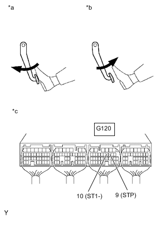
*a Brake Pedal Depressed *b Brake Pedal Released *c Component with harness connected
(ECM)
Turn the ignition switch to ON.
-
Measure the voltage according to the value(s) in the table below.
Standard Voltage Tester Connection Brake Pedal Condition Specified Condition G120-10 (ST1-) - Body ground Released 7.5 to 14 V Depressed 0 to 1.5 V G120-9 (STP) - Body ground Released 0 to 1.5 V Depressed 7.5 to 14 V Result Proceed to OK NG
NG
REPAIR OR REPLACE HARNESS OR CONNECTOR Click here
OK
-
-
REPLACE ECM
-
Replace the ECM.
Result Proceed to NEXT
NEXT
GO TO STEP 6 Click here
-
-
REPAIR OR REPLACE HARNESS OR CONNECTOR
-
Repair or replace the harness or connector.
Result Proceed to NEXT
NEXT
-
-
CONFIRM WHETHER MALFUNCTION HAS BEEN SUCCESSFULLY REPAIRED
-
Connect the GTS to the DLC3.
-
Clear the DTCs.
Powertrain > Engine and ECT > Clear DTCs -
Turn the ignition switch off.
-
Turn the ignition switch to ON and turn the GTS on.
-
Depress and release the brake pedal.
-
Enter the following menus: Powertrain / Engine and ECT / Trouble Codes.
-
Confirm that the DTC is not output again.
Powertrain > Engine and ECT > Trouble CodesResult Proceed to NEXT
NEXT 
END
-
-
REPLACE STOP LIGHT SWITCH ASSEMBLY
-
Replace the stop light switch assembly.
Result Proceed to NEXT
NEXT
GO TO STEP 6 Click here
-