| DTC Code | DTC Name |
|---|---|
| Injector Circuit |
DESCRIPTION
The injector driver drives the injector assembles at high speeds with a high-voltage DC/DC converter. The ECM constantly monitors the injector driver and stops the engine if an abnormal condition is detected.
CAUTION / NOTICE / HINT
-
After replacing the ECM, the new ECM needs registration (See page ) and initialization (Click here).
-
Inspect the fuses of circuits related to this system before performing the following procedure.
PROCEDURE
- Click here
CHECK INJECTOR DRIVER (POWER SOURCE)
-
Disconnect the injector driver connectors.
-
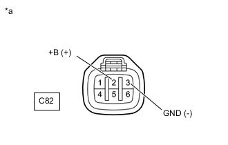
*a Front view of wire harness connector
(to Injector Driver)
Measure the voltage according to the value(s) in the table below.
Standard Voltage Tester Connection Switch Condition Specified Condition C82-2 (+B) - C82-3 (GND) Ignition switch ON 11 to 14 V -
Reconnect the injector driver connector.
Result Proceed to OK NG
- OK
CHECK FOR INTERMITTENT PROBLEMSClick here
- NGClick here
-
- Click here
INSPECT EDU RELAY
-
Inspect the EDU relay from engine room relay block.
Result Proceed to OK NG
- OKClick here
- NG
REPLACE EDU RELAY
-
- Click here
CHECK HARNESS AND CONNECTOR (EDU RELAY - INJECTOR DRIVER)
-
Remove the EDU relay from the engine room relay block and junction block assembly.
-
Disconnect the injector driver connector.
-
Measure the resistance according to the value(s) in the table below.
Standard Resistance Tester Connection Condition Specified Condition C82-2 (+B) - EDU relay tarminal 5 Always Below 1 Ω C82-3 (GND) - Body ground Always Below 1 Ω C82-2 (+B) or EDU relay tarminal 5 - Body ground Always 10 kΩ or higher -
Reconnect the injector driver connector.
-
Reinstall the EDU relay.
Result Proceed to OK NG
- OKClick here
- NG
REPAIR OR REPLACE HARNESS OR CONNECTOR
-
- Click here
CHECK HARNESS AND CONNECTOR (EDU RELAY - ECM)
-
Remove the EDU relay from the engine room relay block and junction block assembly.
-
Disconnect the ECM connector.
-
Measure the resistance according to the value(s) in the table below.
Standard Resistance Tester Connection Condition Specified Condition G84-10 (IREL) - EDU relay tarminal 2 Always Below 1 Ω G84-10 (IREL) or EDU relay tarminal 2 - Bodyground Always 10 kΩ or higher -
Reconnect the ECM connector.
-
Reinstall the EDU relay.
Result Proceed to OK NG
- OK
REPLACE ECMClick here
- NG
REPAIR OR REPLACE HARNESS OR CONNECTOR
-