ECD SYSTEM ECM Power Source Circuit
DESCRIPTION
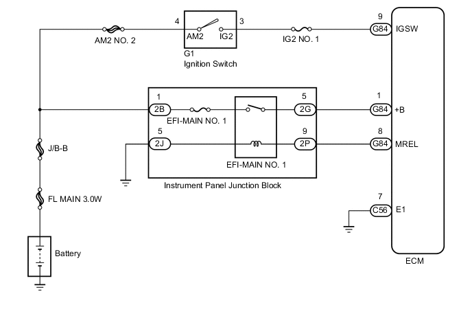
When the ignition switch is turned to ON, the battery voltage is applied to terminal IGSW of the ECM. The MREL output signal from ECM causes a current to flow to the coil, closing the contacts of the MAIN relay and supplying power to terminal +B of the ECM.
WIRING DIAGRAM
Figure 1. w/ Entry and Start System
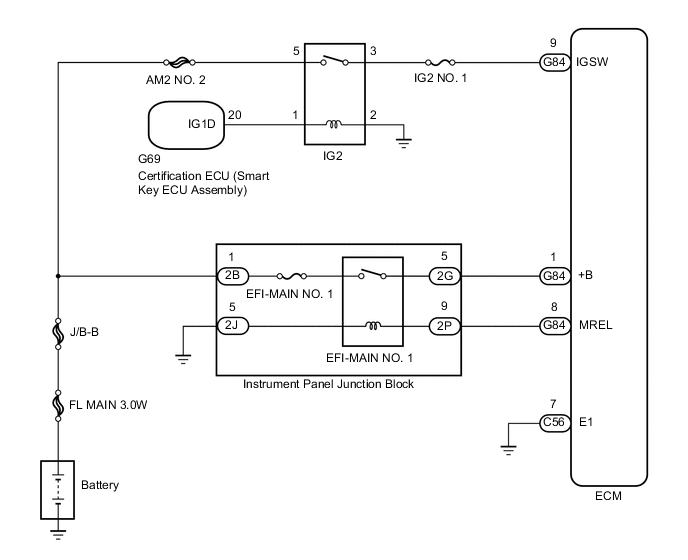
Figure 2. w/o Entry and Start System
CAUTION / NOTICE / HINT
Note
-
After replacing the ECM, the new ECM needs registration (See page ) and initialization Click here.
-
Inspect the fuses of circuits related to this system before performing the following procedure.
PROCEDURE
-
INSPECT ECM (+B VOLTAGE)
-
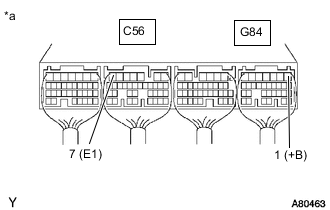
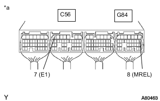
*a Component with harness connected
(ECM)
Measure the voltage according to the value(s) in the table below.
Standard Voltage Tester Connection Condition Specified Condition G84-1 (+B) - C56-7 (E1) IG ON 11 to 14 V Result Proceed to OK NG
OK 
PROCEED TO NEXT SUSPECTED AREA SHOWN IN PROBLEM SYMPTOMS TABLE Click here
NG 
-
-
CHECK HARNESS AND CONNECTOR (ECM - BODY GROUND)
-
Disconnect the ECM connector.
-
Measure the resistance according to the value(s) in the table below.
Standard Resistance Tester Connection Condition Specified Condition C56-7 (E1) - Body ground Always Below 1 Ω -
Reconnect the ECM connector.
Result Proceed to OK NG
NG
REPAIR OR REPLACE HARNESS OR CONNECTOR
OK
-
-
INSPECT ECM (IGSW VOLTAGE)
-
Turn the ignition switch to ON.
-
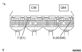
*a Component with harness connected
(ECM)
Measure the voltage according to the value(s) in the table below.
Standard Voltage Tester Connection Switch Condition Specified Condition G84-9 (IGSW) - C56-7 (E1) Ignition switch ON 11 to 14 V Result Proceed to OK NG (w/o Entry and Start System) NG (w/ Entry and Start System)
NG (w/o Entry and Start System) 
INSPECT IGNITION SWITCH Click here
NG (w/ Entry and Start System)
INSPECT IG2 RELAY Click here
OK
-
-
INSPECT ECM (MREL VOLTAGE)
-
Turn the ignition switch to ON.
-
*a Component with harness connected
(ECM)
Measure the voltage according to the value(s) in the table below.
Standard Voltage Tester Connection Switch Condition Specified Condition G84-8 (MREL) - C56-7 (E1) Ignition switch ON 11 to 14 V Result Proceed to OK NG
NG
REPLACE ECM Click here
OK
-
-
INSPECT INSTRUMENT PANEL JUNCTION BLOCK ASSEMBLY (EFI-MAIN NO. 1 RELAY)
-
Inspect the instrument panel junction block assembly (EFI-MAIN NO. 1 relay).
Result Proceed to OK NG
NG
REPLACE EFI-MAIN NO. 1 RELAY
OK
-
-
CHECK HARNESS AND CONNECTOR (EFI-MAIN NO. 1 RELAY - ECM, EFI-MAIN NO. 1 RELAY - BODY GROUND)
-
Check the harness and connector between the instrument panel junction block (EFI-MAIN NO. 1 relay) and ECM.
-
Disconnect the instrument panel junction block connector.
-
Disconnect the ECM connector.
-
Measure the resistance according to the value(s) in the table below.
Standard Resistance Tester Connection Condition Specified Condition 2G-5 - G84-1 (+B) Always Below 1 Ω 2P-9 - G84-8 (MREL) Always Below 1 Ω 2G-5 or G84-1 (+B) - Body ground Always 10 kΩ or higher 2P-9 or G84-8 (MREL) - Body ground Always 10 kΩ or higher -
Reconnect the ECM connector.
-
Reconnect the instrument panel junction block connector.
-
-
Check the harness and connector between the instrument panel junction block (EFI-MAIN NO. 1 relay) and body ground.
-
Disconnect the instrument panel junction block connector.
-
Measure the resistance according to the value(s) in the table below.
Standard Resistance Tester Connection Condition Specified Condition 2J-5 - Body ground Always Below 1 Ω -
Reconnect the instrument panel junction block connector.
Result Proceed to OK NG -
OK
REPAIR OR REPLACE HARNESS OR CONNECTOR (BATTERY - MAIN RELAY)
NG
REPAIR OR REPLACE HARNESS OR CONNECTOR
-
-
INSPECT IGNITION SWITCH
-
Disconnect the ignition switch connector.
-
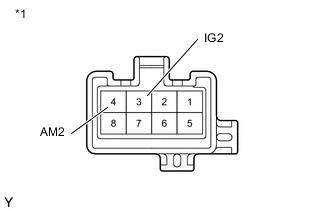
*1 Ignition Switch Measure the resistance according to the value(s) in the table below.
Standard Resistance Tester Connection Switch Condition Specified Condition 4 (AM2) - 3 (IG2) LOCK 10 kΩ or higher 4 (AM2) - 3 (IG2) ON Below 1 Ω -
Reconnect the ignition switch connector.
Result Proceed to OK NG
OK
REPAIR OR REPLACE HARNESS OR CONNECTOR (BATTERY - IGNITION SWITCH, IGNITION SWITCH - ECM)
NG
REPLACE IGNITION SWITCH Click here
-
-
INSPECT IG2 RELAY
-
Inspect the IG2 relay.
Result Proceed to OK NG
NG
REPLACE IG2 RELAY
OK
-
-
CHECK HARNESS AND CONNECTOR (IG2 RELAY - ECM)
-
Disconnect the ECM connector.
-
Remove the IG2 relay from No. 4 instrument panel relay block.
-
Measure the resistance according to the value(s) in the table below.
Standard Resistance Tester Connection Condition Specified Condition G84-9 (IGSW) - IG2 Relay terminal 3 Always Below 1 Ω G84-9 (IGSW) or IG2 Relay terminal 3 - Body ground and other terminals Always 10 kΩ or higher -
Reconnect the ECM connector.
-
Reinstall the IG2 relay.
Result Proceed to OK NG
NG
REPAIR OR REPLACE HARNESS OR CONNECTOR
OK
-
-
CHECK TERMINAL VOLTAGE (IG2 RELAY)
-
Remove the IG2 relay from No. 4 instrument panel relay block.
-
Measure the voltage according to the value(s) in the table below.
Standard Voltage Tester Connection Switch Condition Specified Condition IG2 Relay terminal 5 - Body ground Always 11 to 14 V Result Proceed to OK NG
NG
REPAIR OR REPLACE HARNESS OR CONNECTOR
OK
-
-
CHECK HARNESS AND CONNECTOR (CERTIFICATION ECU - IG2 RELAY)
-
Disconnect the certification ECU (smart key ECU assembly) connector.
-
Remove the IG2 relay from No. 4 instrument panel relay block.
-
Measure the resistance according to the value(s) in the table below.
Standard Resistance Tester Connection Condition Specified Condition G69-20 (IG1D) - IG2 Relay terminal 1 Always Below 1 Ω IG2 Relay terminal 2 - Body ground Always Below 1 Ω G69-20 (IG1D) or IG2 Relay terminal 1 - Body ground and other terminals Always 10 kΩ or higher -
Reconnect the certification ECU (smart key ECU assembly) connector.
-
Reinstall the IG2 relay.
Result Proceed to OK NG
OK
REPLACE CERTIFICATION ECU (SMART KEY ECU ASSEMBLY)
NG
REPAIR OR REPLACE HARNESS OR CONNECTOR
-