RELAY(w/ Urea SCR System) ON-VEHICLE INSPECTION
CAUTION / NOTICE / HINT
The necessary procedures (adjustment, calibration, initialization, or registration) that must be performed after parts are removed, installed, or replaced during the body ECU removal/installation are shown below.
| Replacement Part or Procedure | Necessary Procedures | Effects/Inoperative when not Performed | Link |
|---|---|---|---|
| Replacement of body ECU | Initialize automatic light control system | Automatic light control system |
PROCEDURE
-
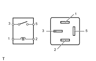
INSPECT EDU RELAY (EDU)
-
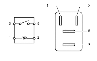
Measure the resistance according to the value(s) in the table below.
Standard Resistance Tester Connection Condition Specified Condition 3 - 5 Battery voltage not applied to terminals 1 and 2 10 kΩ or higher Battery voltage applied to terminals 1 and 2 Below 1 Ω If the result is not as specified, replace the EDU relay.
-
-
INSPECT IG2 RELAY (IG2)
-
Measure the resistance according to the value(s) in the table below.
Standard Resistance Tester Connection Condition Specified Condition 3 - 5 Battery voltage not applied to terminals 1 and 2 10 kΩ or higher Battery voltage applied to terminals 1 and 2 Below 1 Ω If the result is not as specified, replace the IG2 relay.
-
-
INSPECT NOX PM RELAY (NOX PM)
-
Measure the resistance according to the value(s) in the table below.
Standard Resistance Tester Connection Condition Specified Condition 3 - 5 Battery voltage not applied to terminals 1 and 2 10 kΩ or higher Battery voltage applied to terminals 1 and 2 Below 1 Ω If the result is not as specified, replace the NOX PM relay.
-
-
INSPECT DCU RELAY (DCU)
-
Measure the resistance according to the value(s) in the table below.
Standard Resistance Tester Connection Condition Specified Condition 3 - 5 Battery voltage not applied to terminals 1 and 2 10 kΩ or higher Battery voltage applied to terminals 1 and 2 Below 1 Ω If the result is not as specified, replace the DCU relay.
-
-
INSPECT INSTRUMENT PANEL JUNCTION BLOCK ASSEMBLY
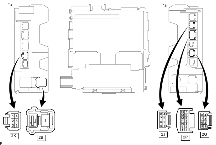
*a Component without harness connected
(Instrument Panel Junction Block Assembly)
- - Note
Before performing the relay inspections for the relays of the instrument panel junction block assembly, inspect the EFI-MAIN NO. 1, EFI-MAIN NO. 2 and EFI NO. 1 fuses.
-
Remove the instrument panel junction block assembly.
-
for LHD:
-
for RHD:
-
-
Remove the body ECU from the instrument panel junction block assembly.
-
for LHD:
-
for RHD:
-
-
Inspect the EFI-MAIN NO. 1 relay.
-
Measure the resistance according to the value(s) in the table below.
Standard Resistance Tester Connection Condition Specified Condition 2B-1 - 2G-5 Battery voltage not applied to terminals 2P-8 and 2K-3 10 kΩ or higher Battery voltage applied to terminals 2P-8 and 2K-3 Below 1 Ω If the result is not as specified, replace the instrument panel junction block assembly.
-
-
Inspect the EFI-MAIN NO. 2 relay.
-
Measure the resistance according to the value(s) in the table below.
Standard Resistance Tester Connection Condition Specified Condition 2B-1 - 2G-3 Battery voltage not applied to terminals 2P-9 and 2J-5 10 kΩ or higher Battery voltage applied to terminals 2P-9 and 2J-5 Below 1 Ω If the result is not as specified, replace the instrument panel junction block assembly.
-
-
Install the body ECU to the instrument panel junction block assembly.
-
for LHD:
-
for RHD:
-
-
Install the instrument panel junction block assembly.
-
for LHD:
-
for RHD:
-
-