ECD SYSTEM, Diagnostic DTC:P1251
| DTC Code | DTC Name |
|---|---|
| P1251 | Step Motor for Turbocharger Control Circuit (Intermittent) |
DESCRIPTION
Tech Tips
Refer to DTC P0046 Click here.
| DTC No. | Detection Item | DTC Detection Condition | Trouble Area | MIL | Memory |
|---|---|---|---|---|---|
| P1251 | Turbocharger / Supercharger Overboost Condition (Too High) | Boost pressure is higher than the threshold* for 0.5 seconds. (1 trip detection logic). |
|
Comes on | DTC stored |
Tech Tips
*: This value changes based on engine speed, atmospheric pressure and the engine coolant temperature (the value is generally between 177 and 250 kPa).
| DTC No. | Data List |
|---|---|
| P1251 |
|
Tech Tips
If DTC P1251 is stored due to the VN turbo vane being stuck closed, the following symptoms may appear:
-
Vehicle surge when driving with full load
-
Sudden lack of power due to power being limited
CONFIRMATION DRIVING PATTERN
| DTC Detection Drive Pattern | Vehicle being driven |
WIRING DIAGRAM
Refer to DTC P0046 Click here.
CAUTION / NOTICE / HINT
Tech Tips
Read freeze frame data using the GTS. Freeze frame data records the engine condition when malfunctions are detected. When troubleshooting, freeze frame data can help determine if the vehicle was moving or stationary, if the engine was warmed up or not, and other data from the time the malfunction occurred.
Note
After replacing the ECM, the new ECM needs registration (See page ) and initialization Click here.
PROCEDURE
-
CHECK FOR ANY OTHER DTCS OUTPUT (RECORD STORED DTC AND FREEZE FRAME DATA)
-
Connect the GTS to the DLC3.
-
Turn the ignition switch to ON and turn the GTS on.
-
Enter the following menus: Powertrain / Engine / Trouble Codes.
Powertrain > Engine > Trouble Codes -
Read the DTCs.
Tech Tips
-
Record the stored DTC and Freeze Frame Data.
-
Be sure to carefully examine "MAP" and "Target Booster Pressure" in the freeze frame data.
Result Result Proceed to P1251 is output A P1251 and other DTCs are output B Tech Tips
DC motor-related DTCs: P0046 (See page), P0047 and P0048 Click here.
Nozzle vane position sensor-related DTCs: P2563, P2564, P2565, P2588 and P2589 Click here.
-
B 
GO TO DTC CHART Click here
A 
-
-
CHECK AIR INTAKE SYSTEM
-
Check if the hoses between the air cleaner and turbocharger, and turbocharger and intake manifold are damaged or disconnected.
Result Result Proceed to Hoses or pipes are damaged or disconnected A No hoses or pipes are damaged or disconnected B Tech Tips
-
Be sure to check if the hoses and pipes between the air cleaner and compressor are disconnected as disconnection of a hose or pipe can cause overboost. Also, check the high pressure hoses for disconnection due to overboost.
-
Check for disconnection of the exhaust pipes.
-
Using your hand, check whether the pipes and hoses in the intake system are securely connected.
-
Check for any modifications in the intake system made by the user.
-
B 
GO TO STEP 4 Click here
A
-
-
REPAIR OR REPLACE AIR INTAKE SYSTEM
-
Repair or replace the malfunctioning part in the air intake system.
Result Proceed to NEXT
NEXT
-
-
CHECK TURBOCHARGER SUB-ASSEMBLY (DC MOTOR OPERATION)
-
Turn the ignition switch to ON.
-
Turn the ignition switch off and check the DC motor operation (check the operation link movement).
Tech Tips
When it is necessary to repeat this inspection, wait 30 seconds or more with the ignition switch off before performing the inspection.
OK When ignition switch is turned off, operation link moves as shown in A through D in illustration below. Operation link and motor rod move smoothly when moving from position shown in A to that shown in B, and from position shown in B to that shown in C. 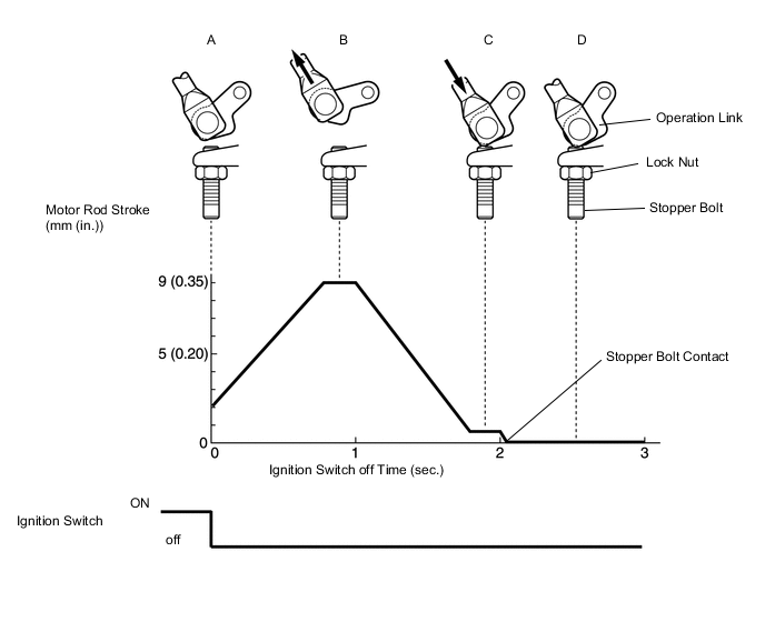
Result Proceed to OK NG
NG
CHECK HARNESS AND CONNECTOR (TURBO MOTOR DRIVER - TURBOCHARGER SUB-ASSEMBLY) Click here
OK
-
-
READ VALUE USING GTS (INJECTION VOLUME)
-
Connect the GTS to the DLC3.
-
Start the engine and warm it up until the engine coolant temperature reaches 75°C (167°F) or higher.
-
Allow the engine to idle for 1 minute or more.
Tech Tips
The A/C switch and all accessory switches should be off with a fully warm engine.
-
Turn the GTS on.
-
Enter the following menus: Powertrain / Engine / Data List / Injection Volume.
Powertrain > Engine > Data ListTester Display Injection Volume -
Read the values during engine idling.
Result Result Proceed to Injection Volume is less than 4 mm3/st
A Except above B Tech Tips
-
If the injector assembly is malfunctioning, the compensatory injection volume remains at 5.0 mm3/st.
-
If there is a disconnection, the feedback value will increase and +5.0 mm3/st will be indicated, because it will become impossible for the injector to inject.
-
B
GO TO STEP 9 Click here
A
-
-
REPLACE INJECTOR ASSEMBLIES OF ALL CYLINDERS
-
Replace the injector assemblies.
Result Proceed to NEXT
NEXT
-
-
BLEED AIR FROM FUEL SYSTEM
-
Bleed the air from the fuel system.
Result Proceed to NEXT
NEXT
-
-
REGISTER INJECTOR COMPENSATION CODE AND PERFORM PILOT QUANTITY LEARNING
-
Register the injector compensation code.
-
Perform the injector pilot quantity learning.
Result Proceed to NEXT
NEXT
-
-
CONFIRM WHETHER MALFUNCTION HAS BEEN SUCCESSFULLY REPAIRED
-
Connect the GTS to the DLC3.
-
Turn the ignition switch to ON and turn the GTS on.
-
Clear the DTCs.
Powertrain > Engine > Clear DTCs -
Start the engine.
-
Drive the vehicle with a city driving pattern at least 10 minutes.
-
Confirm the value of Engine Speed from the Freeze Frame Data recorded previously, and then drive the vehicle according to the Engine Speed value.
Tech Tips
Take a snapshot of MAP and Target Boost Pressure in the Data List with the GTS while driving the vehicle.
-
Enter the following menus: Powertrain / Engine / Trouble Codes.
Powertrain > Engine > Trouble Codes -
Read the DTCs.
Result Result Proceed to P1251 is not output and the amount by which MAP exceeds Target Boost Pressure is 20 kPa or less A Except above B
*
Tech Tips
*: Return to "Check Air Intake System" and inspect areas that have not been inspected yet.
A
END
B
GO TO STEP 2 Click here
-
-
CHECK HARNESS AND CONNECTOR (TURBO MOTOR DRIVER - TURBOCHARGER SUB-ASSEMBLY)
-
Disconnect the DC motor connector.
-
Disconnect the nozzle vane position sensor connector.
-
Disconnect the turbo motor driver connector.
-
Measure the resistance according to the value(s) in the table below.
Standard Resistance Tester Connection Condition Specified Condition C91-2 (M+) - C90-12 (M+) Always Below 1 Ω C91-1 (M-) - C90-5 (M-) Always Below 1 Ω C92-1 (VTA1) - C90-9 (VTA1) Always Below 1 Ω C92-2 (VNE2) - C90-8 (VNE2) Always Below 1 Ω C92-3 (VNVC) - C90-1 (VNVC) Always Below 1 Ω C92-4 (VTA2) - C90-10 (VTA2) Always Below 1 Ω C92-5 (E2S) - C90-11 (E2S) Always Below 1 Ω C92-6 (VCS) - C90-6 (VCS) Always Below 1 Ω C91-2 (M+) or C90-12 (M+) - Body ground Always 10 kΩ or higher C91-1 (M-) or C90-5 (M-) - Body ground Always 10 kΩ or higher C92-1 (VTA1) or C90-9 (VTA1) - Body ground Always 10 kΩ or higher C92-2 (VNE2) or C90-8 (VNE2) - Body ground Always 10 kΩ or higher C92-3 (VNVC) or C90-1 (VNVC) - Body ground Always 10 kΩ or higher C92-4 (VTA2) or C90-10 (VTA2) - Body ground Always 10 kΩ or higher C92-5 (E2S) or C90-11 (E2S) - Body ground Always 10 kΩ or higher C92-6 (VCS) or C90-6 (VCS) - Body ground Always 10 kΩ or higher -
Reconnect the DC motor connector.
-
Reconnect the nozzle vane position sensor connector.
-
Reconnect the turbo motor driver connector.
Result Proceed to OK NG
OK
INSPECT TURBOCHARGER SUB-ASSEMBLY Click here
NG
REPAIR OR REPLACE HARNESS OR CONNECTOR
-