KNOCK SENSOR REMOVAL
CAUTION / NOTICE / HINT
The necessary procedures (adjustment, calibration, initialization, or registration) that must be performed after parts are removed, installed, or replaced during the knock sensor removal/installation are shown below.
| Replacement Part or Procedure | Necessary Procedures | Effects/Inoperative when not Performed | Link |
|---|---|---|---|
| Replacement of knock sensor | Inspection After Repair | Poor idle, engine start, etc. |
PROCEDURE
-
REMOVE CYLINDER HEAD SUB-ASSEMBLY RH (for Bank 1)
-
REMOVE NO. 1 WATER OUTLET PIPE
-
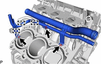
Detach the 3 wire harness clamps.
-
for Type A:
Remove the 3 bolts and No. 1 water outlet pipe.
-
for Type B:
Remove the 2 nuts, bolt and No. 1 water outlet pipe.
-
-
REMOVE KNOCK SENSOR
-
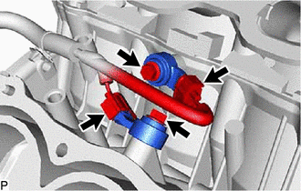
Disconnect the 2 knock sensor connectors.
-
Remove the 2 bolts and 2 knock sensors.
-