| DTC Code | DTC Name |
|---|---|
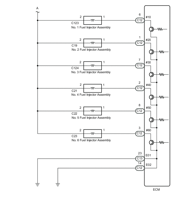
| Fuel Injector Circuit |
DESCRIPTION
The fuel injector assemblies are located on the intake port. They inject fuel into the cylinders based on the signals from the ECM.
CAUTION / NOTICE / HINT
Inspect the fuses for circuits related to this system before performing the following procedure.
PROCEDURE
-
*a Front view of wire harness connector (to Fuel Injector Assembly)Click here
CHECK TERMINAL VOLTAGE (POWER SOURCE OF FUEL INJECTOR ASSEMBLY)
-
Disconnect the fuel injector assembly connectors.
-
Turn the ignition switch to ON.
-
Measure the voltage according to the value(s) in the table below.
Standard Voltage Tester Connection Condition Specified Condition C123-2 - Body ground Ignition switch ON 11 to 14 V C19-2 - Body ground Ignition switch ON 11 to 14 V C124-2 - Body ground Ignition switch ON 11 to 14 V C21-2 - Body ground Ignition switch ON 11 to 14 V C22-2 - Body ground Ignition switch ON 11 to 14 V C23-2 - Body ground Ignition switch ON 11 to 14 V Result Proceed to OK NG
- OKClick here
- NGClick here
-
- Click here
INSPECT FUEL INJECTOR ASSEMBLY
-
Inspect the fuel injector assembly.
Result Proceed to OK NG
- OKClick here
- NG
REPLACE FUEL INJECTOR ASSEMBLYClick here
-
- Click here
CHECK HARNESS AND CONNECTOR (FUEL INJECTOR ASSEMBLY - ECM)
-
Disconnect the fuel injector assembly connectors.
-
Disconnect the ECM connector.
-
Measure the resistance according to the value(s) in the table below.
Standard Resistance Tester Connection Condition Specified Condition C123-1 - C12-6 (#10) Always Below 1 Ω C19-1 - C12-1 (#20) Always Below 1 Ω C124-1 - C12-7 (#30) Always Below 1 Ω C21-1 - C12-2 (#40) Always Below 1 Ω C22-1 - C12-8 (#50) Always Below 1 Ω C23-1 - C12-3 (#60) Always Below 1 Ω C123-1 or C12-6 (#10) - Body ground and other terminals Always 10 kΩ or higher C19-1 or C12-1 (#20) - Body ground and other terminals Always 10 kΩ or higher C124-1 or C12-7 (#30) - Body ground and other terminals Always 10 kΩ or higher C21-1 or C12-2 (#40) - Body ground and other terminals Always 10 kΩ or higher C22-1 or C12-8 (#50) - Body ground and other terminals Always 10 kΩ or higher C23-1 or C12-3 (#60) - Body ground and other terminals Always 10 kΩ or higher Result Proceed to OK NG
- OK
PROCEED TO NEXT SUSPECTED AREA SHOWN IN PROBLEM SYMPTOMS TABLEClick here
- NG
REPAIR OR REPLACE HARNESS OR CONNECTOR
-
- Click here
CHECK HARNESS AND CONNECTOR (INJ RELAY - FUEL INJECTOR ASSEMBLY)
-
Remove the INJ relay from the engine room relay block and junction block assembly.
-
Disconnect the fuel injector assembly connectors.
-
Measure the resistance according to the value(s) in the table below.
Standard Resistance Tester Connection Condition Specified Condition INJ relay terminal 3 - C123-2 Always Below 1 Ω INJ relay terminal 3 - C19-2 Always Below 1 Ω INJ relay terminal 3 - C124-2 Always Below 1 Ω INJ relay terminal 3 - C21-2 Always Below 1 Ω INJ relay terminal 3 - C22-2 Always Below 1 Ω INJ relay terminal 3 - C23-2 Always Below 1 Ω INJ relay terminal 3 or C123-2 - Body ground and other terminals Always 10 kΩ or higher INJ relay terminal 3 or C19-2 - Body ground and other terminals Always 10 kΩ or higher INJ relay terminal 3 or C124-2 - Body ground and other terminals Always 10 kΩ or higher INJ relay terminal 3 or C21-2 - Body ground and other terminals Always 10 kΩ or higher INJ relay terminal 3 or C22-2 - Body ground and other terminals Always 10 kΩ or higher INJ relay terminal 3 or C23-2 - Body ground and other terminals Always 10 kΩ or higher Result Proceed to OK NG
- OK
GO TO ECM POWER SOURCE CIRCUITClick here
- NG
REPAIR OR REPLACE HARNESS OR CONNECTOR
-