HYBRID CONTROL SYSTEM, Diagnostic DTC:P2601-777
| DTC Code | DTC Name |
|---|---|
| P2601-777 | Oil Pump Control Range / Performance |
DESCRIPTION
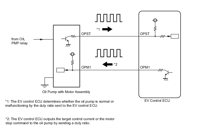
The EV control ECU detects drive motor temperature based on signals from the drive motor temperature sensor and activates the OIL PMP relay and oil pump driver (oil pump with motor assembly).
The EV control ECU monitors OPST signals from the oil pump driver and detects malfunctions.
| DTC No. | Detection Item | DTC Detection Condition | Trouble Area | Warning Indicate |
|---|---|---|---|---|
| P2601-777 | Oil Pump Control Range / Performance | Command signal (OPM1) from EV control ECU is abnormal (1 trip detection logic) |
|
Master Warning Light: Comes on |
| DTC No. | Data List |
|---|---|
| P2601-777 |
|
The oil pump assembly with motor activates when the temperature of the drive motor is 85°C (185°F) or more:
Tech Tips
The oil pump with motor assembly cannot be activated only with the OIL PMP relay on. It is activated after receiving the command signals (OPM1) from the EV control ECU.
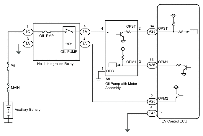
WIRING DIAGRAM
CAUTION / NOTICE / HINT
Note
When the vehicle is parked with the power switch off, if the FC control ECU judges that the FC stack temperature will go below 0°C (32°F), it activates the FC air compressor, hydrogen pump and FC cooling water pump for a maximum of 180 seconds and drains water from the FC stack assembly. When performing inspection or repairs with the power switch off (not on (IG) or on (READY)), disconnect the cable from the negative (-) auxiliary battery terminal before performing work (If the auxiliary battery voltage is needed to conduct inspection, warm up the FC system beforehand).
Tech Tips
-
When troubleshooting the oil pump with motor assembly, check for the following conditions.
-
ATF temperature inside the oil cooler is 5°C (41°F) or more.
-
The ambient temperature sensor value is 5°C (41°F) or more.
-
After the repair, clear the DTCs and perform the following procedure to check that DTCs are not output.
-
Turn the power switch on (IG).
-
Enter inspection mode.
Tech Tips
Entering inspection mode activates the oil pump with motor assembly.
-
Turn the power switch on (READY) and wait for 5 seconds or more.
PROCEDURE
-
CHECK OIL PUMP WITH MOTOR ASSEMBLY
-
Connect the GTS to the DLC3.
-
Turn the power switch on (IG).
-
Enter inspection mode.
Tech Tips
Entering inspection mode activates the oil pump with motor assembly.
-
Turn the power switch on (IG).
-
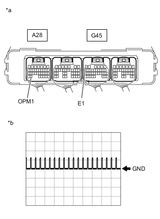
*a Component with harness connected
(EV control ECU)
*b Normal Waveform Connect an oscilloscope between the EV control ECU terminals specified in the table below, and measure the waveform.
Item Content Terminal A28-33 (OPM1) - G45-6 (E1) Equipment Setting 10 V/DIV., 20 ms/DIV. Condition Inspection mode
Power switch on (READY)
Result Result Proceed to Normal waveform is output. A No waveform (0 V) B No waveform (12 V) C Other than above. D -
Turn the power switch off.
A 
REPLACE OIL PUMP WITH MOTOR ASSEMBLY Click here
C 
CHECK HARNESS AND CONNECTOR (EV CONTROL ECU - OIL PUMP WITH MOTOR ASSEMBLY) Click here
D
REPLACE EV CONTROL ECU Click here
B 
-
-
CHECK HARNESS AND CONNECTOR (EV CONTROL ECU - OIL PUMP WITH MOTOR ASSEMBLY)
-
Disconnect the oil pump with motor assembly connector.
-
Disconnect the EV control ECU connector.
-

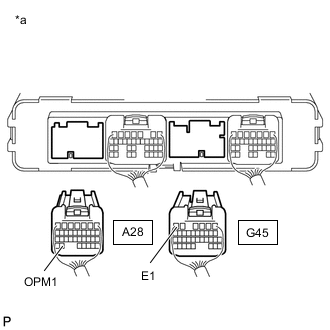
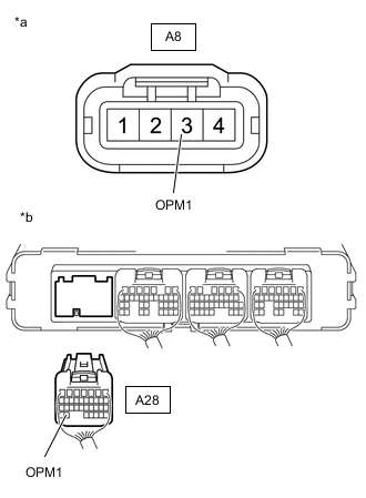
*a Front view of wire harness connector
(to Oil Pump with Motor Assembly)
*b Rear view of wire harness connector
(to EV Control ECU)
Measure the resistance according to the value(s) in the table below.
Standard Resistance Tester Connection Switch Condition Specified Condition A8-3 (OPM1) - A28-33 (OPM1) Power switch off Below 1 Ω A8-3 (OPM1) or A28-33 (OPM1) - Body ground and other terminals Power switch off 10 kΩ or higher -
Reconnect the EV control ECU connector.
-
Reconnect the oil pump with motor assembly connector.
Result Proceed to OK NG
NG
REPAIR OR REPLACE HARNESS OR CONNECTOR
OK
-
-
CHECK OIL PUMP WITH MOTOR ASSEMBLY
-
Disconnect the EV Control ECU connector.
-
*a Rear view of wire harness connector
(to EV Control ECU)
Measure the resistance according to the value(s) in the table below.
Standard Resistance Tester Connection Switch Condition Specified Condition A28-33 (OPM1) - G45-6 (E1) Power switch off 10 kΩ or higher -
Reconnect the EV Control ECU connector.
Result Proceed to OK NG
OK
REPLACE EV CONTROL ECU Click here
NG
REPLACE OIL PUMP WITH MOTOR ASSEMBLY Click here
-
-
CHECK HARNESS AND CONNECTOR (EV CONTROL ECU - OIL PUMP WITH MOTOR ASSEMBLY)
-
Disconnect the Oil Pump with Motor Assembly connector.
-
Disconnect the EV control ECU connector.
-
Turn the power switch on (IG).
-
*a Front view of wire harness connector
(to Oil Pump with Motor Assembly)
*b Rear view of wire harness connector
(to EV Control ECU)
Measure the voltage according to the value(s) in the table below.
Standard Voltage Tester Connection Switch Condition Specified Condition A8-3 (OPM1) or A28-33 (OPM1) - Body ground Power switch on (IG) Below 1 V Tech Tips
Turning the power switch on (IG) with the EV control ECU connector disconnected causes other DTCs to be stored. Clear the DTCs after performing this inspection.
-
Turn the power switch off.
-
Reconnect the EV control ECU connector.
-
Reconnect the oil pump with motor assembly.
Result Proceed to OK NG
NG
REPAIR OR REPLACE HARNESS OR CONNECTOR
OK
-
-
INSPECT OIL PUMP WITH MOTOR ASSEMBLY
-
Disconnect the A8 oil pump with motor assembly connector.
-
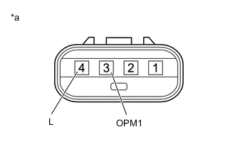
*a Component without harness connected
(Oil Pump with Motor Assembly)
Measure the resistance according to the value(s) in the table below.
Standard Resistance Tester Connection Switch Condition Specified Condition 3 (OPM1) - 4 (L) Power switch off 10 kΩ or higher -
Reconnect the oil pump with motor assembly.
Result Proceed to OK NG
OK
REPLACE EV CONTROL ECU Click here
NG
REPLACE OIL PUMP WITH MOTOR ASSEMBLY Click here
-