HYBRID CONTROL SYSTEM, Diagnostic DTC:P2532-772
| DTC Code | DTC Name |
|---|---|
| P2532-772 | Ignition Switch Run Position Circuit High |
DESCRIPTION
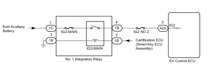
The EV control ECU monitors the IGSW signals sent from the smart key ECU assembly (certification ECU) and detects a malfunction.
Tech Tips
If DTC P2532-772 is stored, the vehicle will turn off (READY off).
| DTC No. | Detection Item | DTC Detection Condition | Trouble Area | Warning Indicate |
|---|---|---|---|---|
| P2532-772 | Ignition Switch Run Position Circuit High | When communication is lost from ECU that has IG1 circuit power supply and power is supplied to IG2 terminal (1 trip detection logic) |
|
Master Warning Light: Comes on |
WIRING DIAGRAM
CAUTION / NOTICE / HINT
Note
When the vehicle is parked with the power switch off, if the FC control ECU judges that the FC stack temperature will go below 0°C (32°F), it activates the FC air compressor, hydrogen pump and FC cooling water pump for a maximum of 180 seconds and drains water from the FC stack assembly. When performing inspection or repairs with the power switch off (not on (IG) or on (READY)), disconnect the cable from the negative (-) auxiliary battery terminal before performing work (If the auxiliary battery voltage is needed to conduct inspection, warm up the FC system beforehand).
Tech Tips
After the repair, clear the DTCs and perform the following procedure to check that DTCs are not output.
-
Turn the power switch on (IG) and wait for 15 seconds or more.
-
Turn the power switch off and wait for 3 minutes or more.
PROCEDURE
-
CHECK DTC OUTPUT (EV)
-
Connect the GTS to the DLC3.
-
Turn the power switch on (IG).
-
Enter the following menus: Powertrain / EV / Trouble Codes.
-
Check for DTCs.
Powertrain > EV > Trouble CodesResult Result Proceed to P2532-772 only is output. A DTCs except P2532-772 are output. B -
Turn the power switch off.
B 
GO TO STEP 6 Click here
A 
-
-
READ VALUE USING GTS (CAN BUS CHECK)
-
Connect the GTS to the DLC3.
-
Turn the power switch on (IG).
-
Enter the following menus: System Select / CAN Bus Check.
CAN Bus CheckResult Result Proceed to All of the ECUs and sensors that are currently connected to the CAN communication system are displayed. A None of the ECUs and sensors that are currently connected to the CAN communication system are displayed, or some of them are not displayed.(for LHD) B None of the ECUs and sensors that are currently connected to the CAN communication system are displayed, or some of them are not displayed.(for RHD) C -
Turn the power switch off.
B 
GO TO CAN COMMUNICATION SYSTEM (for LHD) Click here
C
GO TO CAN COMMUNICATION SYSTEM (for RHD) Click here
A
-
-
CHECK HARNESS AND CONNECTOR (+B SHORT)
-
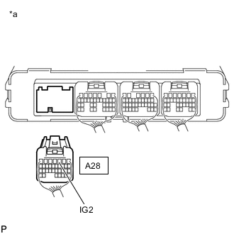
*a Rear view of wire harness connector
(to EV Control ECU)
Disconnect the EV control ECU connector.
-
Measure the voltage according to the value(s) in the table below.
Standard Voltage Tester Connection Condition Specified Condition A28-3 (IG2) - Body ground Power switch off 1 V or less -
Reconnect the EV control ECU connector.
Result Proceed to OK NG
OK
REPLACE EV CONTROL ECU Click here
NG
-
-
INSPECT NO. 1 INTEGRATION RELAY (IG2-MAIN)
-

*1 Motor Compartment Relay Block *2 No. 1 Integration Relay Remove the No. 1 integration relay from the motor compartment relay block.
-
Inspect the IG2-MAIN relay (No. 1 integration relay).
-
Install the No. 1 integration relay.
Result Proceed to OK NG
NG
REPLACE NO. 1 INTEGRATION RELAY (IG2-MAIN)
OK
-
-
CHECK HARNESS AND CONNECTOR (EV CONTROL ECU - IG2-MAIN RELAY)
-
Disconnect the EV control ECU connector.
-
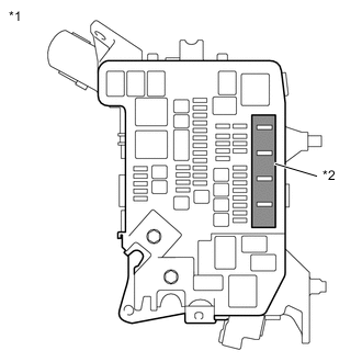
*1 Motor Compartment Relay Block *2 No. 1 Integration Relay Remove the No. 1 integration relay from the motor compartment relay block.
-
*a Rear view of wire harness connector
(to EV Control ECU)
Measure the voltage according to the value(s) in the table below.
Standard Voltage Tester Connection Condition Specified Condition A28-3 (IG2) - Body ground Power switch off Below 1 V -
Install the No. 1 integration relay.
-
Reconnect the EV control ECU connector.
Result Proceed to OK NG
NG
REPAIR OR REPLACE HARNESS OR CONNECTOR
OK
-
-
CHECK FOR INTERMITTENT PROBLEMS
-
Check for intermittent problems.
-
Check the connection and terminal contact pressure of the connectors and wire harnesses between the EV control ECU and the motor compartment relay block.
-
When the power switch is on (READY), jiggle the connectors and wire harnesses between the EV control ECU and the motor compartment relay block.
Result Result Proceed to Problem symptom does not recur. A Problem symptom recurs. B -
A
REPLACE EV CONTROL ECU Click here
B
REPAIR OR REPLACE MALFUNCTIONING PARTS, COMPONENT AND AREA
-