HYBRID CONTROL SYSTEM, Diagnostic DTC:P2511-149
| DTC Code | DTC Name |
|---|---|
| P2511-149 | EV CPU Power Relay Sense Circuit Intermittent No Continuity |
DESCRIPTION
This DTC indicates that the EV control ECU detected an instantaneous interruption in +B power source voltage.
| DTC No. | Detection Item | DTC Detection Condition | Trouble Area | Warning Indicate |
|---|---|---|---|---|
| P2511-149 | EV CPU Power Relay Sense Circuit Intermittent No Continuity | When the power switch is on (READY), the EV control ECU is reset due to an instantaneous interruption of power source. (1 trip detection logic) |
|
Master Warning Light: Comes on |
WIRING DIAGRAM
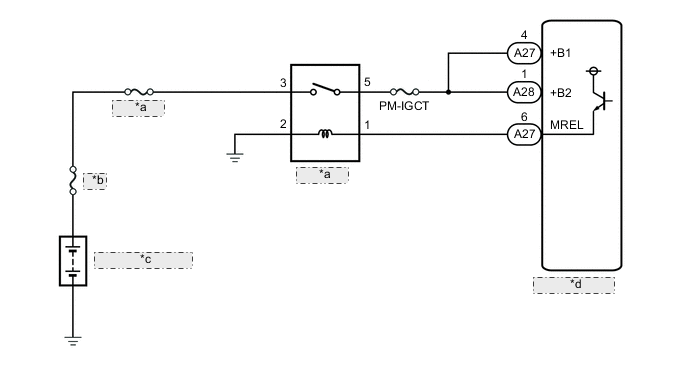
| *a | IGCT NO.1 |
| *b | MAIN |
| *c | Auxiliary Battery |
| *d | EV Control ECU |
CAUTION / NOTICE / HINT
Note
When the vehicle is parked with the power switch off, if the FC control ECU judges that the FC stack temperature will go below 0°C (32°F), it activates the FC air compressor, hydrogen pump and FC cooling water pump for a maximum of 180 seconds and drains water from the FC stack assembly. When performing inspection or repairs with the power switch off (not on (IG) or on (READY)), disconnect the cable from the negative (-) auxiliary battery terminal before performing work (If the auxiliary battery voltage is needed to conduct inspection, warm up the FC system beforehand).
Tech Tips
After the repair, clear the DTCs and perform the following procedure to check that DTCs are not output.
-
Turn the power switch on (READY) and wait for 30 seconds or more.
(If the DTC is not output, drive the vehicle on urban roads according to the freeze frame data item "Vehicle Speed" for approximately 5 minutes.)
PROCEDURE
-
CHECK AUXILIARY BATTERY TERMINAL
-
Confirm whether the auxiliary battery terminals have been disconnected recently.
Result Result Proceed to Terminals have been disconnected. A Terminals have not been disconnected. B
B 
GO TO STEP 5 Click here
A 
-
-
CONFIRM MASTER WARNING LIGHT
-
Turn the power switch on (READY) from off.
-
Confirm that the master warning light illuminates.
Result Result Proceed to Master warning light illuminates. A Master warning light does not illuminates. B Note
DTC P2511-149 may be stored after disconnecting and reconnecting the auxiliary battery terminals. If this happens, the DTC will not be output if the power switch is turned off and then on (READY) again. In this case, clear DTCs to complete the inspection.
-
Turn the power switch off.
B 
END
A
-
-
CLEAR DTC
Result Proceed to NEXT
-
Connect the GTS to the DLC3.
-
Turn the power switch on (IG).
-
Enter the following menus: Powertrain / EV / Trouble Codes.
-
Read and record the DTCs and freeze frame data.
Powertrain > EV > Trouble Codes -
Clear the DTCs and freeze frame data.
Powertrain > EV > Clear DTCs -
Turn the power switch off and wait 3 minutes or more.
Result Proceed to NEXT
NEXT
-
-
CHECK DTC OUTPUT (EV)
-
Connect the GTS to the DLC3.
-
Turn the power switch on (IG).
-
Enter the following menus: Powertrain / EV / Trouble Codes.
-
Check for DTCs.
Powertrain > EV > Trouble CodesResult Result Proceed to DTC P2511-149 is output again. A DTCs other than P2511-149 are also output. B -
Turn the power switch off.
B
GO TO DTC CHART (HYBRID CONTROL SYSTEM) Click here
A
-
-
CHECK AUXILIARY BATTERY TERMINAL (CONTACT PROBLEM)
-
Check the connection of the auxiliary battery terminal.
OK The terminal is connected securely and there is no contact problem. Result Proceed to OK NG
NG
CONNECT SECURELY
OK
-
-
CHECK CONNECTOR CONNECTION CONDITION (EV CONTROL ECU CONNECTOR)
Result Proceed to OK NG
-
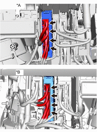
*A for LHD *B for RHD Check the connector connections and contact pressure of the relevant terminals for the EV control ECU connectors.
OK The connectors are connected securely and there are no contact pressure problems. Result Proceed to OK NG
NG
CONNECT SECURELY
OK
-
-
CHECK HARNESS AND CONNECTOR (EV CONTROL ECU - IGCT NO.1 RELAY)
-
Remove the IGCT NO.1 relay from the motor compartment relay block.
-
Disconnect the EV control ECU connectors.
-
Measure the resistance according to the value(s) in the table below.
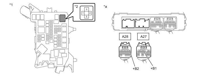
*1 Motor Compartment Relay Block *2 IGCT NO.1 Relay Holder *a Rear view of wire harness connector
(to EV Control ECU)
- - Standard Resistance Tester Connection Condition Specified Condition A27-4 (+B1) - 5 (IGCT NO.1 relay holder) Power switch off Below 1 Ω A28-1 (+B2) - 5 (IGCT NO.1 relay holder) Power switch off Below 1 Ω -
Install the IGCT NO.1 relay.
-
Reconnect the EV control ECU connectors.
Result Proceed to OK NG
NG
REPAIR OR REPLACE HARNESS OR CONNECTOR
OK
-
-
CHECK FOR INTERMITTENT PROBLEMS
-
Check for intermittent problems.
-
Check the connection and terminal contact pressure of the connectors and wire harnesses between the EV control ECU and the motor compartment relay block.
-
When the power switch is on (READY), jiggle the connectors and wire harnesses between the EV control ECU and the motor compartment relay block.
Result Result Proceed to Problem symptom does not recur. A Problem symptom recurs. B -
A
REPLACE EV CONTROL ECU Click here
B
REPAIR OR REPLACE MALFUNCTIONING PARTS, COMPONENT AND AREA
-