HYBRID CONTROL SYSTEM, Diagnostic DTC:P0AC0-817
| DTC Code | DTC Name |
|---|---|
| P0AC0-817 | Battery Pack Current Sensor Circuit Range/Performance |
DESCRIPTION
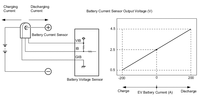
A battery current sensor is installed to the positive (+) cable side of the EV battery and detects current flowing from the EV battery. The battery current sensor outputs voltage, which changes between 0 and 5 V according to the detected amperage, to the IB terminal of the battery voltage sensor. The battery voltage sensor sends signals to the EV control ECU. The EV control ECU determines the charging and discharging amount of the EV battery based on the received signals and calculates the SOC of the EV battery through the accumulated amperage.
| DTC No. | Detection Item | DTC Detection Condition | Trouble Area | Warning Indicate |
|---|---|---|---|---|
| P0AC0-817 | Battery Pack Current Sensor Circuit Range/Performance | Abnormal battery current sensor characteristics: An abnormality in the battery current sensor characteristics is detected based on the relationship between hybrid system power consumption and battery power output. (1 trip detection logic) |
|
Master Warning Light: Comes on |
| DTC No. | Data List |
|---|---|
| P0AC0-817 | - |
CAUTION / NOTICE / HINT
Note
When the vehicle is parked with the power switch off, if the FC control ECU judges that the FC stack temperature will go below 0°C (32°F), it activates the FC air compressor, hydrogen pump and FC cooling water pump for a maximum of 180 seconds and drains water from the FC stack assembly. When performing inspection or repairs with the power switch off (not on (IG) or on (READY)), disconnect the cable from the negative (-) auxiliary battery terminal before performing work (If the auxiliary battery voltage is needed to conduct inspection, warm up the FC system beforehand).
Tech Tips
After the repair, clear the DTCs and perform the following procedure to check that DTCs are not output.
-
Drive the vehicle for approximately 10 minutes according to the freeze frame data items "Vehicle Speed", "Accelerator Degree", "IB-Battery Current", "Drive Motor Execution Torque" and "FC Air Compressor Motor Torque".
PROCEDURE
-
CHECK DTC OUTPUT (EV)
-
Connect the GTS to the DLC3.
-
Turn the power switch on (IG).
-
Enter the following menus: Powertrain / EV / Trouble Codes.
-
Check for DTCs.
Powertrain > EV > Trouble CodesResult Result Proceed to P0AC0-817 only is output. A P0AFC-123 is output. B U1160-450 is output. C -
Turn the power switch off.
B 
GO TO DTC CHART (P0AFC-123) Click here
C
GO TO DTC CHART (U1160-450) Click here
A 
-
-
REPLACE EV BATTERY JUNCTION BLOCK ASSEMBLY
Result Proceed to NEXT
NEXT
-
CLEAR DTC
Result Proceed to NEXT
-
Connect the GTS to the DLC3.
-
Turn the power switch on (IG).
-
Enter the following menus: Powertrain / EV / Trouble Codes.
-
Read and record the DTCs and freeze frame data.
Powertrain > EV > Trouble Codes -
Clear the DTCs and freeze frame data.
Powertrain > EV > Clear DTCs -
Turn the power switch off and wait 3 minutes or more.
Result Proceed to NEXT
NEXT
-
-
PERFORM ROAD TEST
-
Drive the vehicle for approximately 10 minutes according to the freeze frame data items "Vehicle Speed", "Accelerator Degree", "IB-Battery Current", "Drive Motor Execution Torque" and "FC Air Compressor Motor Torque".
CAUTION:
When performing the confirmation driving pattern, obey all speed limits and traffic laws.
Result Proceed to NEXT
NEXT
-
-
CHECK DTC OUTPUT (EV)
-
Connect the GTS to the DLC3.
-
Turn the power switch on (IG).
-
Enter the following menus: Powertrain / EV / Trouble Codes.
-
Check for DTCs.
Powertrain > EV > Trouble CodesResult Result Proceed to P0AC0-817 is not output. A P0AC0-817 is output again. B -
Turn the power switch off.
A
COMPLETED
B
REPLACE BATTERY VOLTAGE SENSOR Click here
-