HYBRID CONTROL SYSTEM, Diagnostic DTC:P0A94-587
| DTC Code | DTC Name |
|---|---|
| P0A94-587 | Boosting Converter Performance |
DTC SUMMARY
-
MALFUNCTION DESCRIPTION
The EV control ECU detects a VB sensor or VL sensor malfunction.
The cause of this malfunction may be one of the following:
-
Voltage sensor malfunction
-
Motor generator control ECU (MG ECU) malfunction
-
Communication (wire harness) malfunction
Inside of inverter voltage sensor circuit malfunction
-
EV battery malfunction
-
EV battery junction block assembly malfunction
-
Inverter with converter assembly malfunction
-
High-voltage wire harness malfunction
-
High-voltage connector or connection malfunction
High voltage system malfunction
-
-
Inspection Overview
Inspection Content Reason (Narrow Down in Order Using Inspection Procedures Below) Inspection Step Check for DTCs (EV) Output DTCs 1 Check for DTCs (check voltage sensor malfunction locations)
Check for DTCs (drive test)
Put vehicle in ready ON (vehicle stopped or being driven) and then check whether DTCs are output again. 3 Check freeze frame data (EV) FREEZE FRAME DATA 4, 5 Read value using GTS Data List value 6
DESCRIPTION
For a description of the boost converter.
The MG ECU uses a voltage sensor (VL) that is built into the boost converter to detect the high voltage before it is boosted. The ECU also uses the battery voltage sensor to detect EV battery voltage (VB).
Tech Tips
Using the GTS, check the Data List values of "Power Resource VB" and "Batt Pack Current Val".
If these values are not within the range below, there is a malfunction in the battery voltage sensor circuit.
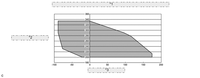
| *1 | EV Battery Voltage to EV Battery Current 20 to 40°C (68 to 104°F) |
| *2 | EV Battery Voltage (V) |
| *3 | EV Battery Current (A) |
| DTC No. | Detection Item | DTC Detection Condition | Trouble Area | Warning Indicate |
|---|---|---|---|---|
| P0A94-587 | Boosting Converter Performance | Voltages from EV battery voltage (VB) sensor and boost converter voltage (VL) sensor deviate: Difference between "VL-Voltage before Boosting" and "Power Resource VB" is large when the boosting request is given. (1 trip detection logic) |
|
Master Warning Light: Comes on |
| DTC No. | Data List |
|---|---|
| P0A94-587 |
|
CAUTION / NOTICE / HINT
Note
When the vehicle is parked with the power switch off, if the FC control ECU judges that the FC stack temperature will go below 0°C (32°F), it activates the FC air compressor, hydrogen pump and FC cooling water pump for a maximum of 180 seconds and drains water from the FC stack assembly. When performing inspection or repairs with the power switch off (not on (IG) or on (READY)), disconnect the cable from the negative (-) auxiliary battery terminal before performing work (If the auxiliary battery voltage is needed to conduct inspection, warm up the FC system beforehand).
Tech Tips
When the accelerator pedal is not depressed with the power switch on (READY) and the shift lever in P, if "VL-Voltage before Boosting" and the "Power Resource VB" is approximately same after repair, the condition is judged as normal.
PROCEDURE
-
CHECK DTC OUTPUT (EV)
-
Connect the GTS to the DLC3.
-
Turn the power switch on (IG).
-
Enter the following menus: Powertrain / EV / Trouble Codes.
-
Check for DTCs.
Powertrain > EV > Trouble CodesResult Result Proceed to
-
Only P0A94-587 is output.
-
DTCs other than "P0A94-442 and DTCs in Chart Below" are output at the same time.
One of the following applies:
A P0A94-587 and P0A94-442 (voltage execution value malfunction) are output at the same time. B DTC indicated in Chart 1 is output at the same time. C DTC indicated in Chart 2 is output at the same time. D Table 1 Malfunction Content Relevant DTC Microcomputer malfunction P0A1B-164, 193, 512, 661, 786 Drive Motor "A" Control Module P0A1D-148 EV Control Module P1D8F-474, 475, 476, 477, 481 FC Air Compressor Motor "A" Control Module P324E-788 Motor CPU Power Relay Sense Circuit Intermittent No Continuity Power source circuit malfunction P2511-149 EV CPU Power Relay Sense Circuit Intermittent No Continuity Communication system malfunction U0110 (all INF codes)*1 Lost Communication with Drive Motor Control Module "A" Sensor and actuator circuit malfunction P0A78-266, 267 Drive Motor "A" Inverter Performance P0A94-585 Boosting Converter Performance P0A94-589, 590 Boosting Converter Performance P0AFC-129 Battery Pack Sensor Module System malfunction P3004-132 High Voltage Power Resource Table 2 Malfunction Content Relevant DTC Microcomputer malfunction P0AFC-123 Battery Pack Sensor Module Sensor and actuator circuit malfunction P0B3D-123 Battery Voltage Sensor "A" Circuit Low P0B42-123 Battery Voltage Sensor "B" Circuit Low P0B47-123 Battery Voltage Sensor "C" Circuit Low P0B4C-123 Battery Voltage Sensor "D" Circuit Low P0B51-123 Battery Voltage Sensor "E" Circuit Low P0B56-123 Battery Voltage Sensor "F" Circuit Low P0B5B-123 Battery Voltage Sensor "G" Circuit Low P0B60-123 Battery Voltage Sensor "H" Circuit Low P0B65-123 Battery Voltage Sensor "I" Circuit Low P0B6A-123 Battery Voltage Sensor "J" Circuit Low P0B6F-123 Battery Voltage Sensor "K" Circuit Low P0B74-123 Battery Voltage Sensor "L" Circuit Low P0B79-123 Battery Voltage Sensor "M" Circuit Low P0B7E-123 Battery Voltage Sensor "N" Circuit Low P0B83-123 Battery Voltage Sensor "O" Circuit Low P0B88-123 Battery Voltage Sensor "P" Circuit Low P0B8D-123 Battery Voltage Sensor "Q" Circuit Low P0B92-123 Battery Voltage Sensor "R" Circuit Low P308A-123 Battery Voltage Sensor All Circuits Low Tech Tips
-
*1: If any INF codes are output for this DTC, refer to the corresponding diagnostic procedure.
-
P0A94-587 may be output as a result of the malfunction indicated by the DTCs above.
-
The chart above is listed in inspection order of priority.
-
Check DTCs that are output at the same time by following the listed order. (The main cause of the malfunction can be determined without performing unnecessary inspections.)
-
-
Turn the power switch off.
B 
REPLACE INVERTER WITH CONVERTER ASSEMBLY Click here
C
GO TO DTC CHART (HYBRID CONTROL SYSTEM) Click here
D
GO TO DTC CHART (HYBRID BATTERY SYSTEM) Click here
A 
-
-
CLEAR DTC
Result Proceed to NEXT
-
Connect the GTS to the DLC3.
-
Turn the power switch on (IG).
-
Enter the following menus: Powertrain / EV / Trouble Codes.
-
Read and record the DTCs and freeze frame data.
Powertrain > EV > Trouble Codes -
Clear the DTCs and freeze frame data.
Powertrain > EV > Clear DTCs -
Turn the power switch off and wait 3 minutes or more.
Result Proceed to NEXT
NEXT
-
-
CHECK DTC OUTPUT (CHECK FAILURE PART)
-
Connect the GTS to the DLC3.
-
Turn the power switch on (READY).
-
Enter the following menus: Powertrain / EV / Data List / IB-Battery Current
Powertrain > EV > Data ListTester Display IB-Battery Current -
In the D range, with the accelerator off (accelerator opening angle fully closed), allow the vehicle to creep forward for 10 seconds continuously, and check that the Data List value "IB-Battery Current" is more than 3 A. (*)
Note
When DTC P0A94-587 is output, the FC system stops generating electricity, so do not perform tests for a long time, and do not perform driving tests on public roads.
-
Leave the vehicle stopped in park (P) for 15 seconds.
Tech Tips
At this point, if DTC P0A94-587 is output, perform the procedure (*) again.
-
Enter the following menus: Powertrain / EV / Trouble codes.
-
Check for DTCs.
Powertrain > EV > Trouble CodesResult Result Proceed to No DTCs are output, or DTCs except the following are output. A P0AFC-129 (Battery Pack Sensor Module) is output. B P0A94-585 (Boosting Converter Performance) is output. C P3004-132 (High Voltage Power Resource) is output. D -
Turn the power switch off.
B
REPLACE BATTERY VOLTAGE SENSOR Click here
C
REPLACE INVERTER WITH CONVERTER ASSEMBLY Click here
D
REPLACE BATTERY VOLTAGE SENSOR Click here
A
-
-
CHECK FREEZE FRAME DATA (EV)
-
Connect the GTS to the DLC3.
-
Turn the power switch on (IG).
-
Enter the following menus: Powertrain / EV / Trouble Codes.
-
Read the freeze frame data of DTC P0A94-587.
Result Result Proceed to Both of the following are satisfied or both of the following are not satisfied. A "VB-Battery Voltage" is less than 204 V or more than 340 V. B "VL-Voltage before Boosting" is less than 204 V or more than 340 V. C -
Turn the power switch off.
B
REPLACE BATTERY VOLTAGE SENSOR Click here
C
REPLACE INVERTER WITH CONVERTER ASSEMBLY Click here
A
-
-
CHECK FREEZE FRAME DATA (EV)
-
Connect the GTS to the DLC3.
-
Turn the power switch on (IG).
-
Enter the following menus: Powertrain / EV / Trouble Codes.
-
Read the freeze frame data of DTC P0A94-587.
Tech Tips
In the freeze frame data, read the item "VB-Battery Voltage" and all of the "Battery Block Voltage".
Result Result Proceed to Both of the following are satisfied:
-
(A) Sum of all "Battery Block Voltage" is more than ("VB-Battery Voltage" -45 V)
-
(B) Sum of all "Battery Block Voltage" is less than ("VB-Battery Voltage" +30 V)
A Neither (A) nor (B) is satisfied. B Freeze frame data is not stored. C -
-
Turn the power switch off.
A
REPLACE INVERTER WITH CONVERTER ASSEMBLY Click here
B
REPLACE BATTERY VOLTAGE SENSOR Click here
C
-
-
READ VALUE USING GTS (DATA LIST)
-
Apply the parking brake and secure the wheels using chocks.
-
Connect the GTS to the DLC3.
-
Turn the power switch on (READY).
-
Enter the following menus: Powertrain / EV / Data List.
-
A FC system stop, move the shift lever to P, and read the "VB-Battery Voltage" and all of the "Battery Block Voltage", with the vehicle is stationary.
Tech Tips
-
FC system stop: The Data List (FC) item "FC Mode" becomes "FC Working" and the item "FC Intermittent Operation" becomes "ON".
-
Using the Techstream Dual Data List function, the EV Data List items and FC Data List items can be checked simultaneously.
Powertrain > EV > Data ListTester Display Battery Block Voltage -V01 Battery Block Voltage -V02 Battery Block Voltage -V03 Battery Block Voltage -V04 Battery Block Voltage -V05 Battery Block Voltage -V06 Battery Block Voltage -V07 Battery Block Voltage -V08 Battery Block Voltage -V09 Battery Block Voltage -V10 Battery Block Voltage -V11 Battery Block Voltage -V12 Battery Block Voltage -V13 Battery Block Voltage -V14 Battery Block Voltage -V15 Battery Block Voltage -V16 Battery Block Voltage -V17 VB-Battery Voltage Result Result Proceed to Both of the following are satisfied:
-
Sum of all "Battery Block Voltage" is more than ("VB-Battery Voltage" -45 V)
-
Sum of all "Battery Block Voltage" is less than ("VB-Battery Voltage" +30 V)
A The preceding condition is not satisfied. B -
-
Turn the power switch off.
A
REPLACE INVERTER WITH CONVERTER ASSEMBLY Click here
B
REPLACE BATTERY VOLTAGE SENSOR Click here
-