COOLANT(for Inverter) REPLACEMENT
PROCEDURE
-
REMOVE FRONT BUMPER LOWER ABSORBER
-
REMOVE NO. 3 RADIATOR AIR GUIDE
-
DRAIN COOLANT (for Inverter)
Note
-
Do not reuse the drained coolant (for inverter) because it may contain foreign matter.
-
Collect the drained coolant (for inverter) and measure its volume to establish a benchmark. When adding coolant (for inverter), make sure to add more coolant (for inverter) than the measured amount.
-
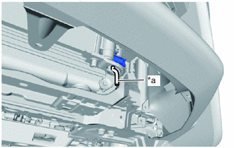
*a Hose Connect a hose with an inside diameter of 9 mm (0.354 in.) to the radiator assembly drain cock as shown in the illustration.
-
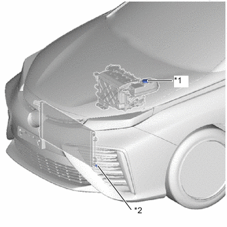
*1 Inverter Reserve Tank Cap *2 Radiator Assembly Drain Cock Plug Remove the inverter reserve tank cap.
-
Loosen the radiator assembly drain cock plug, and drain the coolant (for inverter).
-
Close the radiator assembly drain cock plug.
-
Measure the amount of coolant (for inverter) that was drained.
-
-
ADD COOLANT (for Inverter)
Note
-
Do not reuse the drained coolant (for inverter) because it may contain foreign matter.
-
If the vehicle is driven with air in the inverter cooling system, damage may occur and the following DTCs may be stored.
DTC No. Detection Item P0A01-726 Motor Electronics Coolant Temperature Sensor Circuit Range/Performance P0A04-725 Collision has been detected or Collision Sensor Connection (Open) P0A08-264 DC/DC Converter Status Circuit P0A78-284 Drive Motor "A" Inverter Performance P0A78-286 Drive Motor "A" Inverter Performance P1D82-464 FC Air Compressor Motor Inverter Circuit P1D82-468 FC Air Compressor Motor Inverter Circuit P0A93-346 Inverter Cooling System Performance P0A94-553 Boosting Converter Performance P0A94-557 Boosting Converter Performance P0AEE-277 Motor Inverter Temperature Sensor "A" Circuit Range/Performance P0AF1-276 Motor Inverter Temperature Sensor "A" Circuit Intermittent/Erratic P1D71-450 FC Air Compressor Motor Inverter Temperature Sensor "A" Correlation P1D74-450 FC Air Compressor Motor Inverter Temperature Sensor "A" Correlation P0C39-626 Boosting Converter Temperature Sensor "A" Range/Performance P0C3C-625 Boosting Converter Temperature Sensor "A" Intermittent/Erratic P0C3E-628 Boosting Converter Temperature Sensor "B" Range/Performance P0C41-627 Boosting Converter Temperature Sensor "B" Intermittent/Erratic P0C73-776 Motor Electronics Coolant Pump "A" Control Performance
-
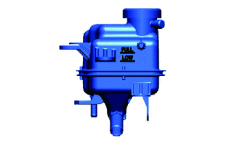
Slowly pour coolant (for inverter) into the inverter reserve tank sub-assembly until it reaches the full line.
Standard Capacity 4.7 liters (5.0 US qts, 4.1 Imp. qts) Note
To prevent foreign matter such as dust or dirt from entering the cooling system, make sure to confirm that the container used to add coolant (for inverter) is clean and free of foreign matter.
-
When using the Techstream:
-
Connect the Techstream to the DLC3.
-
Turn the power switch on (IG).
-
Turn the Techstream on.
-
Enter the following menus: Powertrain / EV /Active Test / Activate the water pump.
-
Perform the "Activate the Water Pump" Active Test.
Powertrain > EV > Active TestTester Display Activate the Water Pump Tech Tips
The EV water pump with motor assembly can also be operated by entering service mode.
-
While adding coolant (for inverter) to the inverter reserve tank sub-assembly to keep the coolant (for inverter) at the full line and compensate for the drop in the coolant (for inverter) level as the air bleeds, operate and stop the EV water pump with motor assembly at 1 minute intervals.
Standard Air bleeding from the inverter cooling system is completed when the noise made by the EV water pump with motor assembly becomes smaller and the circulation of coolant (for inverter) in the inverter reserve tank sub-assembly improves. Tech Tips
-
If free spinning of the EV water pump with motor assembly is detected for approximately 6 seconds, fail-safe control will be activated to suspend the operation of the pump for approximately 15 seconds and resume operation for approximately 4 seconds repeatedly. Operation of the EV water pump with motor assembly will return to normal if coolant (for inverter) is added.
-
Loud noises made by the EV water pump with motor assembly and poor circulation of coolant (for inverter) in the inverter reserve tank sub-assembly indicate that there is air in the cooling system.
-
-
-
When not using the Techstream:
-
Turn the power switch on (READY). [*1]
-
Turn the power switch off and add coolant to the full line because the coolant (for inverter) level drops as the air bleeds. [*2]
Note
-
Be sure to turn the power switch off before adding SLLC.
-
Do not work on the components in the motor compartment while the power switch is on (READY) as the systems will operate intermittently.
-
-
Repeat steps [*1] and [*2] until air bleeding from the cooling system is completed.
Standard Air bleeding from the inverter cooling system is completed when the noise made by the EV water pump with motor assembly becomes smaller and the circulation of coolant (for inverter) in the inverter reserve tank sub-assembly improves. Tech Tips
Loud noises made by the EV water pump with motor assembly and poor circulation of coolant in the inverter reserve tank sub-assembly indicate that there is air in the cooling system.
-
-
After the air is completely bled from the cooling system, add coolant to the full line of inverter reserve tank assembly and install the reserve tank cap.
Note
Check that the amount of coolant (for inverter) that has been added is greater than or equal to the amount that was drained.
-
-
INSPECT FOR COOLANT LEAK (for Inverter)
-
INSTALL NO. 3 RADIATOR AIR GUIDE
-
INSTALL FRONT BUMPER LOWER ABSORBER