FRONT DISC BRAKE PAD INSTALLATION
CAUTION / NOTICE / HINT
Tech Tips
-
Use the same procedure for the RH side and LH side.
-
The following procedure is for the LH side.
PROCEDURE
-
INSTALL NO. 1 PAD WEAR INDICATOR PLATE
-
Install 2 new No. 1 pad wear indicator plates to each front disc brake pad.
Note
Install the No. 1 pad wear indicator plate in the correct positions and directions.
-
-
INSTALL FRONT ANTI-SQUEAL SHIM KIT
-
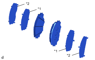
*1 No. 1 Disc Brake Anti-squeal Shim *2 No. 2 Disc Brake Anti-squeal Shim Install the No. 1 disc brake anti-squeal shim and No. 2 disc brake anti-squeal shim to each front disc brake pad.
Note
-
When replacing a worn front disc brake pad, the front anti-squeal shim kit must be replaced together with the front disc brake pad.
-
Install the shims in the correct positions and direction as shown in the illustration.
-
-
-
INSTALL FRONT DISC BRAKE PAD KIT
-
Install the 2 front disc brake pads to the front disc brake cylinder mounting.
Note
-
Make sure there is no oil or grease on the friction surfaces of the front disc brake pads and front disc.
-
Install the front disc brake pad so that the No. 1 pad wear indicator plate is mounted on the upper side of the vehicle.
-
-
Push back the front disc brake piston.
Note
Do not forcibly install the front disc brake piston into the disc brake cylinder assembly.
-
Lift up the disc brake cylinder assembly and install the 2 front disc brake pads to the front disc brake cylinder mounting.
Note
Make sure the friction surfaces of the front disc brake pad and front disc are free of oil and grease.
-
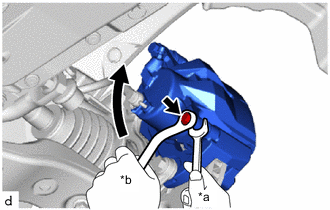
*a Hold *b Turn Hold the front No. 2 disc brake cylinder slide pin and install the disc brake cylinder assembly to the front disc brake cylinder mounting with the bolt.
- Torque:
- 34.3 N*m { 350 kgf*cm, 25 ft.*lbf }
-
Depress the brake pedal several times.
-
-
INSTALL FRONT FLEXIBLE HOSE
-
Install the front flexible hose to the steering knuckle.
- Torque:
- 18.8 N*m { 192 kgf*cm, 14 ft.*lbf }
-
-
INSTALL FRONT SPEED SENSOR
-
Engage the clamp and install the front speed sensor and front flexible hose to the front shock absorber assembly with the bolt.
- Torque:
- 18.8 N*m { 192 kgf*cm, 14 ft.*lbf }
Note
-
Firmly insert the front speed sensor body into the steering knuckle before tightening the bolt.
-
Do not twist the front speed sensor wire harness and front flexible hose when installing it.
-
-
CONNECT CABLE TO NEGATIVE AUXILIARY BATTERY TERMINAL
-
INSTALL LUGGAGE TRIM SERVICE HOLE COVER
-
ADD BRAKE FLUID
-
BLEED BRAKE LINE
-
INSTALL FRONT WHEEL