HYBRID CONTROL SYSTEM, Diagnostic DTC:P0A78-266, P0A78-267
| DTC Code | DTC Name |
|---|---|
| P0A78-266 | Drive Motor "A" Inverter Performance |
| P0A78-267 | Drive Motor "A" Inverter Performance |
DESCRIPTION
The inverter contains a three-phase bridge circuit, which consists of 6 power transistors (IGBTs) each for the FC air compressor motor and drive motor. The inverter converts high-voltage direct current from the EV battery into three-phase alternating current for the FC air compressor motor and drive motor; it also converts three-phase alternating current supplied by FC air compressor motor and drive motor into direct current for the EV battery. The MG ECU controls the actuation of the power transistors (IGBTs). The inverter transmits information necessary for control, such as amperage and voltage, to the MG ECU.
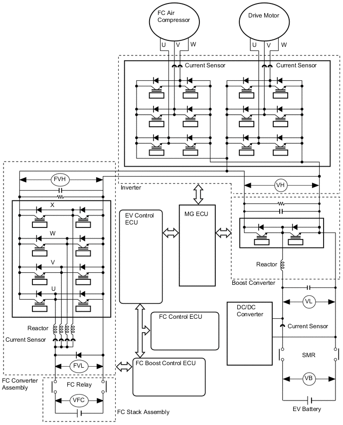
The MG ECU uses an inverter voltage sensor, which is built into the inverter, to detect boosted high voltage (VH) to allow control of the voltage boost.
The inverter voltage sensor outputs voltage that fluctuates between 0 to 5 V according to changes in VH.
The MG ECU monitors the inverter voltage sensor and detects the following malfunctions.
| DTC No. | Detection Item | DTC Detection Condition | Trouble Area | Warning Indicate |
|---|---|---|---|---|
| P0A78-266 | Drive Motor "A" Inverter Performance | Inverter voltage (VH) signal is stuck low: DTC stored when the VH sensor signal is excessively low. (1 trip detection logic) |
Inverter with converter assembly | Master Warning Light: Comes on |
| P0A78-267 | Drive Motor "A" Inverter Performance | Inverter voltage (VH) signal is stuck high: DTC stored when the VH sensor signal is excessively high. (1 trip detection logic) |
Inverter with converter assembly | Master Warning Light: Comes on |
| DTC No. | Data List |
|---|---|
| P0A78-266 | VH-Voltage after Boosting |
| P0A78-267 |
CAUTION / NOTICE / HINT
Note
When the vehicle is parked with the power switch off, if the FC control ECU judges that the FC stack temperature will go below 0°C (32°F), it activates the FC air compressor, hydrogen pump and FC cooling water pump for a maximum of 180 seconds and drains water from the FC stack assembly. When performing inspection or repairs with the power switch off (not on (IG) or on (READY)), disconnect the cable from the negative (-) auxiliary battery terminal before performing work (If the auxiliary battery voltage is needed to conduct inspection, warm up the FC system beforehand).
Tech Tips
After the repair, clear the DTCs and perform the following procedure to check that DTCs are not output.
-
Turn the power switch on (READY) and wait for 5 seconds or more.
PROCEDURE
-
REPLACE INVERTER WITH CONVERTER ASSEMBLY
Tech Tips
The signal line from the inverter voltage (VH) sensor is connected to the MG ECU, which is built into the inverter with converter assembly. If P0A78-266 or P0A78-267 is output, replace the inverter with converter assembly.
Result Proceed to NEXT
NEXT 
COMPLETED