HYBRID CONTROL SYSTEM, Diagnostic DTC:P0A1D-148
| DTC Code | DTC Name |
|---|---|
| P0A1D-148 | EV Control Module |
DESCRIPTION
The EV control ECU monitors its internal operation, it will store a DTC and perform fail-safe control if it detects the following malfunction. If the following DTC is output, replace the EV control ECU.
DTC P0A1D-148 may also be output if a short to +B is detected in the PIBM circuit.
Tech Tips
The FC control ECU activates or wakes up the EV control ECU to perform anti-freeze control of the FC stack. This wake-up power signal circuit is the PIBM circuit.
| DTC No. | Detection Item | DTC Detection Condition | Trouble Area | Warning Indicate |
|---|---|---|---|---|
| P0A1D-148 | EV Control Module | ECU internal malfunction (1 trip detection logic) |
|
Master Warning Light: Comes on |
WIRING DIAGRAM
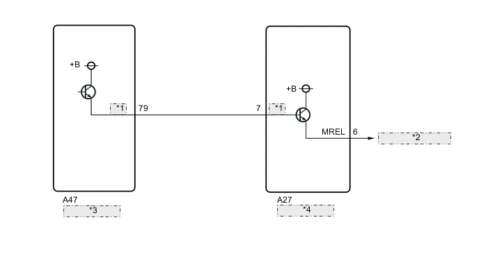
| *1 | PIBM |
| *2 | to IGCT NO.1 Relay |
| *3 | FC Control ECU |
| *4 | EV Control ECU |
Refer to the wiring diagram for ECU Power Source Circuit.
CAUTION / NOTICE / HINT
Note
When the vehicle is parked with the power switch off, if the FC control ECU judges that the FC stack temperature will go below 0°C (32°F), it activates the FC air compressor, hydrogen pump and FC cooling water pump for a maximum of 180 seconds and drains water from the FC stack assembly. When performing inspection or repairs with the power switch off (not on (IG) or on (READY)), disconnect the cable from the negative (-) auxiliary battery terminal before performing work (If the auxiliary battery voltage is needed to conduct inspection, warm up the FC system beforehand).
Tech Tips
After the repair, clear the DTCs and perform the following procedure to check that DTCs are not output.
-
Turn the power switch on (IG) and wait for 1 minute or more.
-
Turn the power switch off and wait for 3 minutes or more.
-
Turn the power switch on (IG) and wait for 30 seconds.
PROCEDURE
-
CHECK DTC OUTPUT (EV)
-
Connect the GTS to the DLC3.
-
Turn the power switch on (IG).
-
Enter the following menus: Powertrain / EV / Trouble Codes.
-
Check for DTCs.
Powertrain > EV > Trouble CodesResult Result Proceed to DTCs except the following are output. A U1161-450 and U1162-450 is output at the same time. B -
Turn the power switch off.
B 
CHECK TERMINAL VOLTAGE (FC CONTROL ECU PIBM TERMINAL VOLTAGE) Click here
A 
-
-
CHECK DTC OUTPUT (RADAR CRUISE)
-
Connect the GTS to the DLC3.
-
Turn the power switch on (IG).
-
Enter the following menus: Powertrain / Radar Cruise / Trouble Codes.
-
Check for DTCs.
Powertrain > Radar Cruise > Trouble CodesResult Result Proceed to C1A40 is not output. A C1A40 is also output. B -
Turn the power switch off.
A
GO TO STEP 4 Click here
B
-
-
CHECK TERMINAL VOLTAGE (FC CONTROL ECU PIBM TERMINAL VOLTAGE)
-
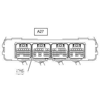
*1 PIBM *a Component with harness connected
(EV Control ECU)
Measure the voltage according to the value(s) in the table below.
Standard Voltage Tester Connection Condition Specified Condition A27-7 (PIBM) - Body ground Power switch off 0 to 1.5 V Result Proceed to OK NG
NG
CHECK TERMINAL VOLTAGE (EV CONTROL ECU PIBM TERMINAL VOLTAGE) Click here
OK
-
-
REPLACE EV CONTROL ECU
Result Proceed to NEXT
NEXT 
COMPLETED
-
CHECK TERMINAL VOLTAGE (EV CONTROL ECU PIBM TERMINAL VOLTAGE)
-
Disconnect the EV control ECU connector.
-
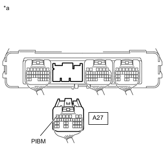
*a Rear view of wire harness connector
(to EV Control ECU)
Measure the voltage according to the value(s) in the table below.
Standard Voltage Tester Connection Condition Specified Condition A27-7 (PIBM) - Body ground Power switch off 0 to 1.5 V Result Proceed to OK NG
NG
CHECK HARNESS AND CONNECTOR (FC CONTROL ECU - EV CONTROL ECU) Click here
OK
-
-
CHECK HARNESS AND CONNECTOR (PIBM SIGNAL WIRE +B SHORT INSPECTION)
-
Disconnect the EV control ECU connector.
-
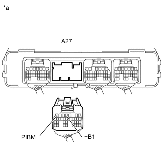
*a Rear view of wire harness connector
(to EV Control ECU)
Measure the resistance according to the value(s) in the table below.
Standard Resistance Tester Connection Condition Specified Condition A27-7 (PIBM) - A27-4 (+B1) Power switch off 10 kΩ or higher -
Reconnect the EV control ECU connector.
Result Proceed to OK NG
OK
REPLACE EV CONTROL ECU Click here
NG
REPAIR OR REPLACE HARNESS OR CONNECTOR
-
-
CHECK HARNESS AND CONNECTOR (FC CONTROL ECU - EV CONTROL ECU)
-
Disconnect the FC control ECU connector.
-
Disconnect the EV control ECU connector.
-
Measure the voltage according to the value(s) in the table below.
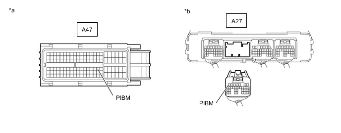
*a Front view of wire harness connector
(to FC Control ECU)
*b Rear view of wire harness connector
(to EV Control ECU)
Standard Voltage Tester Connection Condition Specified Condition A47-79 (PIBM) or A27-7 (PIBM) - Body ground Power switch off 0 to 1.5 V -
Reconnect the EV control ECU connector.
-
Reconnect the FC control ECU connector.
Result Proceed to OK NG
OK
REPLACE FC CONTROL ECU Click here
NG
REPAIR OR REPLACE HARNESS OR CONNECTOR
-