HYBRID CONTROL SYSTEM, Diagnostic DTC:P0851-579, P0852-580
| DTC Code | DTC Name |
|---|---|
| P0851-579 | Park / Neutral Switch Input Circuit Low |
| P0852-580 | Park / Neutral Switch Input Circuit High |
DESCRIPTION
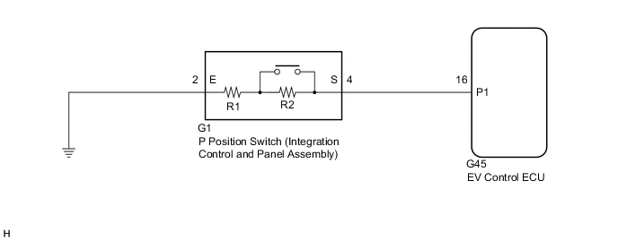
Instead of having a parking position as one of the positions of the conventional shift lever, a P position switch (Integration control and panel assembly) is provided independently above the shift lever. The switch is a momentary type, in which the button does not lock mechanically.
The P position switch (Integration control and panel assembly) contains resistors R1 and R2. When the P position switch is not pressed, the switch provides a combined resistance of R1 and R2; and when the P position switch is pressed, the switch provides only the resistance of R1. The voltage at the P1 terminal of the EV control ECU varies with the changes in the resistance of the switch. The EV control ECU determines the P position switch operation according to this resistance signal.
| DTC No. | Detection Item | DTC Detection Condition | Trouble Area | Warning Indicate |
|---|---|---|---|---|
| P0851-579 | Park / Neutral Switch Input Circuit Low | GND short in P position switch circuit |
|
Master Warning Light: Comes on |
| P0852-580 | Park / Neutral Switch Input Circuit High | Open or +B short in P position switch circuit |
|
Master Warning Light: Comes on |
| DTC No. | Data List |
|---|---|
| P0851-579 |
|
| P0852-580 |
-
*1: While the P position switch is being pressed, the voltage value of the P position switch terminal decreases.
WIRING DIAGRAM
CAUTION / NOTICE / HINT
Note
When the vehicle is parked with the power switch off, if the FC control ECU judges that the FC stack temperature will go below 0°C (32°F), it activates the FC air compressor, hydrogen pump and FC cooling water pump for a maximum of 180 seconds and drains water from the FC stack assembly. When performing inspection or repairs with the power switch off (not on (IG) or on (READY)), disconnect the cable from the negative (-) auxiliary battery terminal before performing work (If the auxiliary battery voltage is needed to conduct inspection, warm up the FC system beforehand).
Tech Tips
After the repair, clear the DTCs and perform the following procedure to check that DTCs are not output.
-
Turn the power switch on (IG) and wait for 5 seconds or more.
PROCEDURE
-
INSPECT INTEGRATION CONTROL AND PANEL ASSEMBLY (P POSITION SWITCH)
-
Disconnect the integration control and panel assembly shift assembly connector.
-
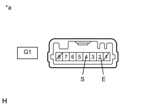
*a Component without harness connected
(P Position Switch (integration control and panel assembly))
Measure the resistance according to the value(s) in the table below.
Standard Resistance Tester Connection Condition Specified Condition G1-4 (S) - G1-2 (E) Switch pressed 646 to 714 Ω G1-4 (S) - G1-2 (E) Switch released 4351 to 4809 Ω Tech Tips
Terminals No. 1 and No. 8 on the component side connector are empty.
-
Reconnect the integration control and panel assembly connector.
Result Proceed to OK NG
NG 
REPLACE INTEGRATION CONTROL AND PANEL ASSEMBLY (P POSITION SWITCH) Click here
OK 
-
-
CHECK HARNESS AND CONNECTOR (EV CONTROL ECU - P POSITION SWITCH (INTEGRATION CONTROL AND PANEL ASSEMBLY))
-
Disconnect the EV control ECU connector.
-
Disconnect the P position switch (integration control and panel assembly) connector.
-
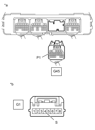
*a Rear view of wire harness connector
(to EV Control ECU)
*b Front view of wire harness connector
(to P Position Switch (Integration Control and Panel Assembly))
Measure the resistance according to the value(s) in the table below.
Standard Resistance Tester Connection Condition Specified Condition G45-16 (P1) - G1-4 (S) Power switch off Below 1 Ω G46-16 (P1) or G1-4 (S) - Body ground and other terminals Power switch off 10 kΩ or higher Tech Tips
As necessary, check that there is no short to power supply wires when performing the above wire harness inspection.
-
Reconnect the P position switch (integration control and panel assembly) connector.
-
Reconnect the EV control ECU connector.
Result Proceed to OK NG
NG
REPAIR OR REPLACE HARNESS OR CONNECTOR
OK
-
-
CHECK HARNESS AND CONNECTOR (P POSITION SWITCH (INTEGRATION CONTROL AND PANEL ASSEMBLY) - BODY GROUND)
-
Disconnect the P position switch (integration control and panel assembly) connector.
-
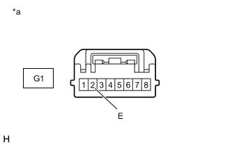
*a Front view of wire harness connector
(to P Position Switch (Integration Control and Panel Assembly))
Measure the resistance according to the value(s) in the table below.
Standard Resistance Tester Connection Condition Specified Condition G1-2 (E) - Body ground Power switch off Below 1 Ω -
Connect the P position switch (integration control and panel assembly) connector.
Result Proceed to OK NG
OK
REPLACE EV CONTROL ECU Click here
NG
REPAIR OR REPLACE HARNESS OR CONNECTOR
-