HYBRID CONTROL SYSTEM, Diagnostic DTC:P085D-582, P085D-599, P0861-597, P0862-598
| DTC Code | DTC Name |
|---|---|
| P085D-582 | Gear Shift Control Module "A" Performance |
| P085D-599 | Gear Shift Control Module "A" Performance |
| P0861-597 | Gear Shift Control Module "A" Communication Circuit Low |
| P0862-598 | Gear Shift Control Module "A" Communication Circuit High |
DESCRIPTION
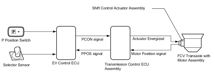
When a signal is input from the P position switch (integration control and panel assembly) or shift lever (transmission instrument panel shift assembly), the EV control ECU transmits a P position control (PCON) signal to the transmission control ECU assembly. Based on this signal, the transmission control ECU assembly actuates the shift control actuator assembly in order to mechanically lock or unlock the counter drive gear in the FCV transaxle with motor assembly.
P position state (engaged or released) of the shift control actuator assembly is sent to the EV control ECU as a P position (PPOS) signal.
| DTC No. | Detection Item | DTC Detection Condition | Trouble Area | Warning Indicate |
|---|---|---|---|---|
| P085D-582 | Gear Shift Control Module "A" Performance | P position (PPOS) signal is logically inconsistent |
|
Master Warning Light: Comes on |
| P085D-599 | Gear Shift Control Module "A" Performance | P position (PPOS) signal malfunction (output pulse is abnormal) |
|
Master Warning Light: Comes on |
| P0861-597 | Gear Shift Control Module "A" Communication Circuit Low | GND short in P position (PPOS) signal circuit |
|
Master Warning Light: Comes on |
| P0862-598 | Gear Shift Control Module "A" Communication Circuit High | +B short in P position (PPOS) signal circuit |
|
Master Warning Light: Comes on |
| DTC No. | Data List |
|---|---|
| P085D-582 |
|
| P085D-599 | |
| P0861-597 | |
| P0862-598 |
WIRING DIAGRAM
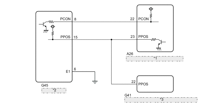
| *1 | Transmission Control ECU Assembly |
| *2 | EV Control ECU |
| *3 | Certification ECU (Smart Key ECU Assembly) |
CAUTION / NOTICE / HINT
Note
When the vehicle is parked with the power switch off, if the FC control ECU judges that the FC stack temperature will go below 0°C (32°F), it activates the FC air compressor, hydrogen pump and FC cooling water pump for a maximum of 180 seconds and drains water from the FC stack assembly. When performing inspection or repairs with the power switch off (not on (IG) or on (READY)), disconnect the cable from the negative (-) auxiliary battery terminal before performing work (If the auxiliary battery voltage is needed to conduct inspection, warm up the FC system beforehand).
Tech Tips
After the repair, clear the DTCs and perform the following procedure to check that DTCs are not output.
-
Turn the power switch on (IG) and wait for 10 seconds or more.
-
While depressing the brake pedal, move the shift lever to N and wait for 10 seconds or more.
-
Push the P position switch (integration control and panel assembly) and wait for 10 seconds or more.
PROCEDURE
-
CHECK DTC OUTPUT (TRANSMISSION CONTROL)
-
Connect the GTS to the DLC3.
-
Turn the power switch on (IG).
-
Enter the following menus: Body Electrical / Transmission Control / Trouble Codes.
Body Electrical > Transmission Control > Trouble Codes -
Check if DTCs are output.
Result Result Proceed to Electronic shift lever system DTCs are not output. A Any of the following DTCs are output. B DTC No. Relevant Diagnosis C2309 Open in B+ Circuit C2311 Communication Error from EV ECU -
Turn the power switch off.
B 
GO TO DTC CHART (ELECTRONIC SHIFT LEVER SYSTEM) Click here
A 
-
-
CHECK HARNESS AND CONNECTOR (EV CONTROL ECU - TRANSMISSION CONTROL ECU)
-
Disconnect the EV control ECU connector.
-
Disconnect the transmission control ECU assembly connector.
-
Disconnect the G41 certification ECU (smart key ECU assembly) connector.
-
Turn the power switch on (IG).
-
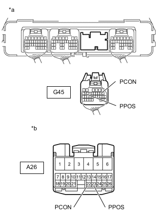
*a Rear view of wire harness connector
(to EV Control ECU)
*b Front view of wire harness connector
(to Transmission Control ECU Assembly)
Measure the voltage according to the value(s) in the table below.
Standard Voltage Tester Connection Condition Specified Condition G45-8 (PCON) - Body ground Power switch on (IG) Below 1 V G45-15 (PPOS) - Body ground Power switch on (IG) Below 1 V Note
Turning the power switch on (IG) with the EV control ECU connectors disconnected causes other DTCs to be stored. Clear the DTCs after performing this inspection.
-
Turn the power switch off.
-
Measure the resistance according to the value(s) in the table below.
Standard Resistance Tester Connection Condition Specified Condition A26-22 (PCON) - G45-8 (PCON) Power switch off Below 1 Ω A26-23 (PPOS) - G45-15 (PPOS) Power switch off Below 1 Ω A26-22 (PCON) or G45-8 (PCON) - Body ground and other terminals Power switch off 10 kΩ or higher A26-23 (PPOS) or G45-15 (PPOS) - Body ground and other terminals Power switch off 10 kΩ or higher -
Reconnect the certification ECU (smart key ECU assembly) connector.
-
Reconnect the transmission control ECU assembly connector.
-
Reconnect the EV control ECU connector.
Result Proceed to OK NG
NG
REPAIR OR REPLACE HARNESS OR CONNECTOR
OK
-
-
CHECK EV CONTROL ECU (PCON SIGNAL)
-
Connect an oscilloscope between the EV control ECU terminals specified in the table below.
-
Turn the power switch on (IG).
-
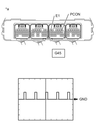
*a Component with harness connected
(EV Control ECU)
Measure the waveform.
Item Content Terminal G45-8 (PCON) - G45-6 (E1) Equipment Setting 10V/DIV., 10ms/DIV. Condition Power switch on (IG) Result Result Proceed to P position control (PCON) signal waveform appears A P position control (PCON) signal waveform does not appear B -
Turn the power switch off.
B
REPLACE EV CONTROL ECU Click here
A
-
-
CHECK EV CONTROL ECU (PPOS SIGNAL)
-
Connect an oscilloscope between the EV control ECU terminals specified in the table below.
-
Turn the power switch on (IG).
-
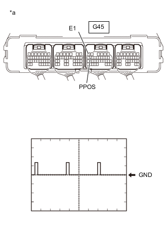
*a Component with harness connected
(EV Control ECU)
Measure the waveform.
Item Content Terminal G45-15 (PPOS) - G45-6 (E1) Equipment Setting 10V/DIV., 10ms/DIV. Condition Power switch on (IG) Result Result Proceed to P position (PPOS) signal waveform appears A P position (PPOS) signal waveform does not appear B -
Turn the power switch off.
B
REPLACE TRANSMISSION CONTROL ECU ASSEMBLY Click here
A
-
-
REPLACE EV CONTROL ECU
Result Proceed to NEXT
NEXT
-
CLEAR DTC
-
Connect the GTS to the DLC3.
-
Turn the power switch on (IG).
-
Enter the following menus: Powertrain / EV / Trouble Codes.
Powertrain > EV > Trouble Codes -
Read and record the DTCs and freeze frame data.
-
Clear DTCs and freeze frame data.
Powertrain > EV > Clear DTCs -
Turn the power switch off and wait for 3 minutes or more.
Result Proceed to NEXT
NEXT
-
-
CHECK DTC OUTPUT (EV)
-
Connect the GTS to the DLC3.
-
Turn the power switch on (IG) and leave the vehicle as it is for 10 seconds.
-
Depress the brake pedal, move the shift lever to N and leave the vehicle as it is for 10 seconds.
-
Push the P position switch (integration control and panel assembly) and leave the vehicle as it is for 10 seconds.
-
Enter the following menus: Powertrain / EV / Trouble Codes.
Powertrain > EV > Trouble Codes -
Check if DTCs are output.
Result Result Proceed to No DTCs are output. A P085D-582, P085D-599, P0861-597 or P0862-598 is output again. B -
Turn the power switch off.
A
COMPLETED
B
REPLACE TRANSMISSION CONTROL ECU ASSEMBLY Click here
-