HYBRID CONTROL SYSTEM, Diagnostic DTC:P0617-142
| DTC Code | DTC Name |
|---|---|
| P0617-142 | Starter Relay Circuit High |
DESCRIPTION
| DTC No. | Detection Item | DTC Detection Condition | Trouble Area | Warning Indicate |
|---|---|---|---|---|
| P0617-142 | Starter Relay Circuit High | An ST signal from the EV control ECU is on when the power switch is off. (2 trip detection logic) |
|
Master Warning Light: Comes on |
WIRING DIAGRAM
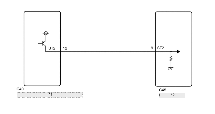
| *1 | Certification ECU (Smart Key ECU Assembly) |
| *2 | EV Control ECU |
CAUTION / NOTICE / HINT
Note
-
Before replacing the certification ECU (smart key ECU assembly), refer to Service Bulletin.
-
When the vehicle is parked with the power switch off, if the FC control ECU judges that the FC stack temperature will go below 0°C (32°F), it activates the FC air compressor, hydrogen pump and FC cooling water pump for a maximum of 180 seconds and drains water from the FC stack assembly. When performing inspection or repairs with the power switch off (not on (IG) or on (READY)), disconnect the cable from the negative (-) auxiliary battery terminal before performing work (If the auxiliary battery voltage is needed to conduct inspection, warm up the FC system beforehand).
Tech Tips
After the repair, clear the DTCs and perform the following procedure to check that DTCs are not output.
-
Turn the power switch off and wait for 3 minutes or more.
-
Turn the power switch on (IG).
-
Turn the power switch off and wait for 3 minutes or more.
PROCEDURE
-
CHECK CONNECTOR CONNECTION CONDITION (EV CONTROL ECU CONNECTOR)
Result Proceed to OK NG
-
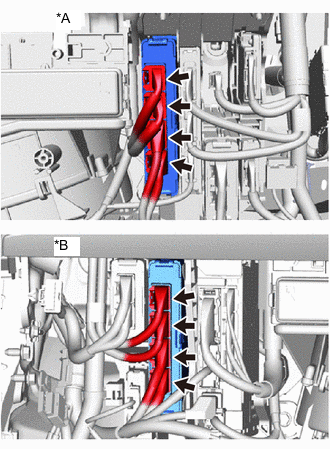
*A for LHD *B for RHD Check the connector connections and contact pressure of the relevant terminals for the EV control ECU connectors.
OK The connectors are connected securely and there are no contact pressure problems. Result Proceed to OK NG
NG 
CONNECT SECURELY
OK 
-
-
CHECK CONNECTOR CONNECTION CONDITION (CERTIFICATION ECU (SMART KEY ECU ASSEMBLY))
-
Check the connector connection condition of the certification ECU (smart key ECU assembly).
Tech Tips
Refer to the Service Bulletin for the installation position.
OK The connector is connected securely and there are no contact problems. Result Proceed to OK NG
NG
CONNECT SECURELY
OK
-
-
CHECK HARNESS AND CONNECTOR (ST2 TERMINAL VOLTAGE)
-
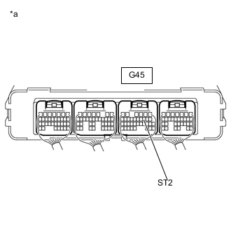
*a Component with harness connected
(EV Control ECU)
Turn the power switch off.
-
Measure the voltage according to the value(s) in the table below.
Standard Voltage Tester Connection Condition Specified Condition G45-9 (ST2) - Body ground Power switch off Below 1 V Result Proceed to OK NG
OK
REPLACE EV CONTROL ECU Click here
NG
-
-
CHECK HARNESS AND CONNECTOR (EV CONTROL ECU - CERTIFICATION ECU (SMART KEY ECU ASSEMBLY))
-
*a Component with harness connected
(EV Control ECU)
Disconnect the G40 certification ECU (smart key ECU assembly) connector.
Tech Tips
Refer to the Service Bulletin for the installation position.
-
Measure the voltage according to the value(s) in the table below.
Standard Voltage Tester Connection Condition Specified Condition G45-9 (ST2) - Body ground Power switch off Below 1 V -
Reconnect the certification ECU (smart key ECU assembly) connector.
Result Proceed to OK NG
OK
REPLACE CERTIFICATION ECU (SMART KEY ECU ASSEMBLY)
NG
REPAIR OR REPLACE HARNESS OR CONNECTOR
-