BLACK OUT TAPE(for Rear Door) INSTALLATION
CAUTION / NOTICE / HINT
Tech Tips
-
Use the same procedure for the RH and LH sides.
-
The procedure listed below is for the LH side.
-
Use the same procedure for RHD and LHD vehicles.
-
The procedure listed below are for RHD vehicles.
PROCEDURE
-
REPAIR INSTRUCTION
-
INSTALL NO. 3 BLACK OUT TAPE LH
Tech Tips
When installing the No. 3 black out tape LH, heat the rear door panel and No. 3 black out tape LH using a heat light.
Standard Item Temperature Rear Door Panel 40 to 60°C (104 to 140°F) No. 3 Black Out Tape LH 20 to 30°C (68 to 86°F) CAUTION:
-
Do not touch the heat light and heated parts.
-
Touching the heat light may result in burns.
-
Touching heated parts for a long time may result in burns.

*a Heated Part *b Heat Light
-
Refer to the illustration to position a new No. 3 black out tape LH.
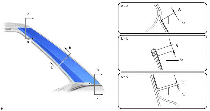
*a Edge of Curved Surface - - Standard Area Specified Condition Area Specified Condition A -1.0 to 1.0 mm (-0.0394 to 0.0394 in.) B 3.0 mm (0.118 in.) C 0 to 2.0 mm (0 to 0.0787 in.) - - -
Remove the release paper from the No. 3 black out tape LH.
-
After installing the No. 3 black out tape LH, remove the unnecessary part above the perforation.
-
-
INSTALL NO. 2 BLACK OUT TAPE LH
Tech Tips
When installing the No. 2 black out tape LH, heat the rear door panel and No. 2 black out tape LH using a heat light.
Standard Item Temperature Rear Door Panel 40 to 60°C (104 to 140°F) No. 2 Black Out Tape LH 20 to 30°C (68 to 86°F) CAUTION:
-
Do not touch the heat light and heated parts.
-
Touching the heat light may result in burns.
-
Touching heated parts for a long time may result in burns.
*a Heated Part *b Heat Light
-
Refer to the illustration to position a new No. 2 black out tape LH.
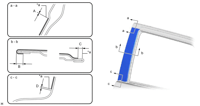
*a Edge of Curved Surface - - Standard Area Specified Condition Area Specified Condition A -1.0 to 1.0 mm (-0.0394 to 0.0394 in.) B 3.0 to 5.0 mm (0.118 to 0.197 in.) C 3.0 mm (0.118 in.) D 0 to 2.0 mm (0 to 0.0787 in.) -
Remove the release paper from the No. 2 black out tape LH.
-
After installing the No. 2 black out tape LH, remove the unnecessary part above the perforation.
-
-
INSTALL REAR DOOR WEATHERSTRIP LH
-
INSTALL REAR DOOR BELT MOULDING ASSEMBLY LH
-
INSTALL REAR DOOR REAR BELT MOULDING LH
-
INSTALL REAR DOOR QUARTER WINDOW GLASS LH
-
INSTALL REAR DOOR GLASS SUB-ASSEMBLY LH
-
INSTALL REAR DOOR WINDOW DIVISION BAR SUB-ASSEMBLY LH
-
INSTALL REAR DOOR GLASS RUN LH
-
INSTALL REAR DOOR SERVICE HOLE COVER LH
-
INSTALL REAR DOOR TRIM BOARD SUB-ASSEMBLY LH
-
INSTALL REAR DOOR INSIDE HANDLE BEZEL PLUG LH
-
INSTALL COURTESY LIGHT ASSEMBLY (w/ Courtesy Light)
-
INSTALL REAR POWER WINDOW REGULATOR SWITCH ASSEMBLY WITH REAR DOOR ARMREST BASE PANEL
-
INSTALL REAR ARMREST ASSEMBLY LH
-
INSTALL REAR DOOR FRAME GARNISH LH
-
CONNECT CABLE TO NEGATIVE BATTERY TERMINAL
Note
When disconnecting the cable, some systems need to be initialized after the cable is reconnected.