AUTOMATIC LIGHT CONTROL SENSOR ON-VEHICLE INSPECTION
PROCEDURE
-
INSPECT AUTOMATIC LIGHT CONTROL SENSOR
-
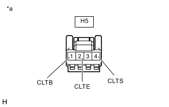
*a Front view of wire harness connector
(to Automatic Light Control Sensor)
Disconnect the automatic light control sensor connector.
-
Measure the voltage and resistance according to the value(s) in the table below.
Standard Voltage Tester Connection Condition Specified Condition H5-1 (CLTB) - H5-2 (CLTE) Engine switch off Below 1 V Engine switch on (IG) 11 to 14 V Standard Resistance Tester Connection Condition Specified Condition H5-2 (CLTE) - Body ground Always Below 1 Ω If the result is not as specified, repair or replace the wire harness.
-
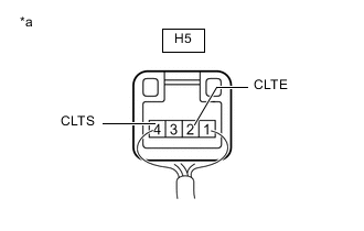
*a Component with harness connected
(Automatic Light Control Sensor)
Reconnect the automatic light control sensor connector.
-
Connect an oscilloscope to the automatic light control sensor connector.
-
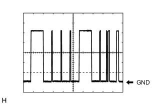
Check the waveform.
OK Tester Connection Tool Setting Condition Specified Condition H5-4 (CLTS) - H5-2 (CLTE) 2 V/DIV., 10 ms./DIV. Ignition switch on (IG), light control switch in AUTO position Correct waveform is as shown Tech Tips
The communication waveform changes according to the surrounding brightness.
If the result is not as specified, replace the automatic light control sensor.
-