LOWER INSTRUMENT PANEL DISASSEMBLY
CAUTION / NOTICE / HINT
Tech Tips
-
Use the same procedure for RHD and LHD vehicles.
-
The procedure listed below is for RHD vehicles.
PROCEDURE
-
REMOVE INSTRUMENT PANEL CUP HOLDER ASSEMBLY (for Driver Side)
-
Detach the claw and guide and remove the cover.
-
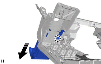

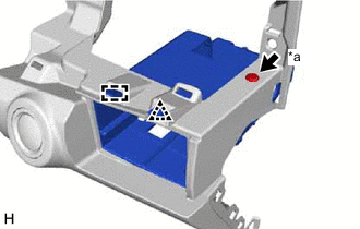
Remove in this Direction Detach the claw and remove the instrument panel cup holder assembly and instrument panel cup holder tray as shown in the illustration.
-
-
REMOVE INSTRUMENT PANEL CUP HOLDER ASSEMBLY (for Passenger Side)
-
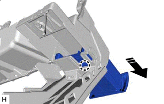
Remove in this Direction Detach the claw and remove the instrument panel cup holder assembly and instrument panel cup holder tray as shown in the illustration.
-
-
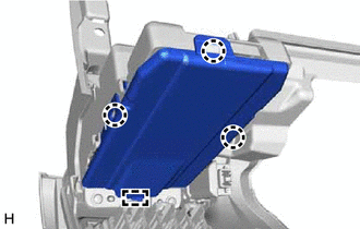
REMOVE INSTRUMENT PANEL CUP HOLDER (for Driver Side)
-
*a Screw <A> Remove the 3 screws <A>.
-
*a Clip <E> Remove the clip <E>.
-
Detach the clip and guide and remove the instrument panel cup holder.
-
-
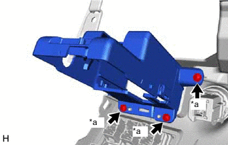
REMOVE INSTRUMENT PANEL CUP HOLDER (for Passenger Side)
-
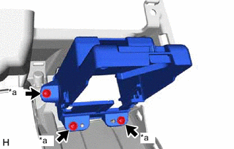
*a Screw <A> Remove the 3 screws <A>.
-
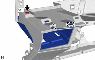
*a Clip <E> Remove the clip <E>.
-
Detach the clip and guide and remove the instrument panel cup holder.
-
-
REMOVE NO. 1 SWITCH HOLE BASE
-
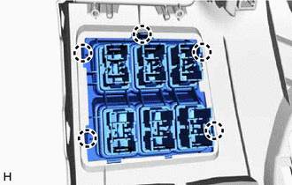
Detach the claw and remove the No. 1 switch hole base.
-
-
REMOVE GLOVE COMPARTMENT DOOR CHECK CUSHION
Tech Tips
Use the same procedure for both glove compartment door check cushions.
-
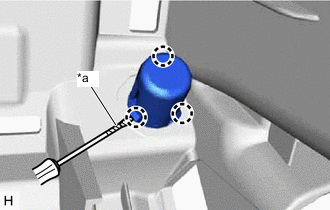
*a Protective Tape Using a screwdriver, detach the claw and remove the glove compartment door check cushion.
Tech Tips
Tape the screwdriver tip before use.
-
-
REMOVE GLOVE COMPARTMENT LOCK CYLINDER ASSEMBLY
Note
Perform this procedure only when replacement of the glove compartment door assembly is necessary.
-
Mark the glove compartment door assembly as shown in the illustration.
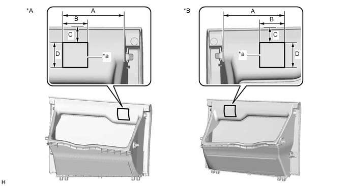
*A for LHD *B for RHD *a Marking - - Standard Measurement Area Measurement Area Measurement A 100.077 mm (3.940 in.) B 50.0 mm (1.969 in.) C 15.0 mm (0.591 in.) D 45.0 mm (1.772 in.) -
Insert a 3.0 mm (0.118 in.) drill bit into a drill.
-
Tape the 3.0 mm (0.118 in.) drill bit 10.0 mm (0.394 in.) from the tip as shown in the illustration.
Note
Tape the 3.0 mm (0.118 in.) drill bit to prevent the drill bit from going too deep.
-
Drill holes along the marking as shown in the illustration.
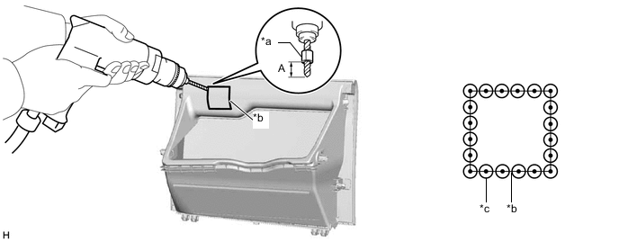
*a Tape *b Marking *c Drilled Hole - - Standard Measurement Area Area A 10.0 mm (0.394 in.) CAUTION:
-
In order to avoid injury, make sure to work carefully so that the tip of the drill does not slip.
-
Make sure to wear protective glasses when performing this procedure as shavings will fly about.
Note
To prevent the glove compartment lock cylinder assembly from being damaged, make sure to only drill holes along the marking.
-
-
Insert a 7.0 mm (0.276 in.) drill bit into a drill.
-
Tape the 7.0 mm (0.276 in.) drill bit 10.0 mm (0.394 in.) from the tip as shown in the illustration.
Note
Tape the 7.0 mm (0.276 in.) drill bit to prevent the drill bit from going too deep.
-
Redrill each hole using the 7.0 mm (0.276 in.) drill bit.
CAUTION:
-
In order to avoid injury, make sure to center the tip of the drill in the pilot hole so that the tip of the drill does not slip.
-
Make sure to wear protective glasses when performing this procedure as shavings will fly about.
-
-
Using a plier nipper (side cutters), cut the glove compartment door assembly between each hole.
-
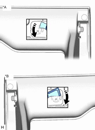
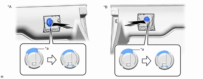
*A for LHD *B for RHD Move in this Direction Move the arm as shown in the illustration.
-
Press the cylinder lock to release it and pull out the glove compartment lock cylinder assembly from the glove compartment door assembly to remove it as shown in the illustration.
*A for LHD *B for RHD *a Cylinder Lock - - Remove in this Direction - -
-