UPPER INSTRUMENT PANEL INSTALLATION
CAUTION / NOTICE / HINT
Tech Tips
-
Use the same procedure for RHD and LHD vehicles.
-
The procedure listed below is for RHD vehicles.
-
A bolt without a torque specification is shown in the standard bolt chart.
PROCEDURE
-
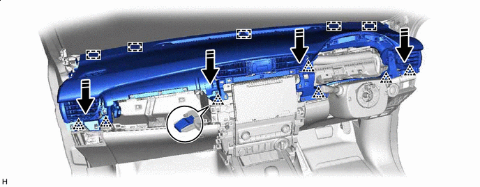
INSTALL UPPER INSTRUMENT PANEL SUB-ASSEMBLY
-
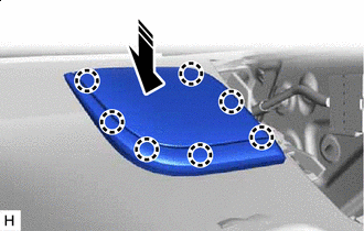
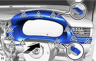
Attach the guide to install the upper instrument panel sub-assembly.
-
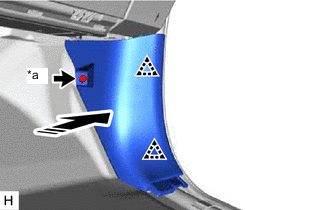
Attach the clip as shown in the illustration.

Install in this Direction - - -
Install the passenger airbag installation bolt <B>.
- Torque:
- 16 N*m { 163 kgf*cm, 12 ft.*lbf }
-
Install the 2 clips <A>.
-
Connect the connector and attach the clamp.
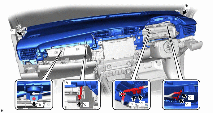
*A w/ Navigation System - - *a Passenger Airbag Installation Bolt <B> *b Clip <A> *c Connector *d Passenger Airbag Connector -
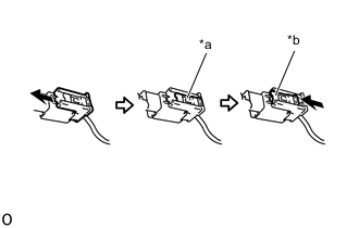
*a Lock Slider *b Lock Position Connect the passenger airbag connector.
Note
When handling the passenger airbag connector, take care not to damage the airbag wire harness.
-
Check that the lock slider is in the lock position.
-
-
INSTALL FRONT NO. 1 SPEAKER BRACKET (for 11 Speakers)
-
INSTALL FRONT NO. 3 SPEAKER ASSEMBLY (for 11 Speakers)
-
INSTALL NO. 2 INSTRUMENT PANEL SPEAKER PANEL SUB-ASSEMBLY (for 11 Speakers)
-
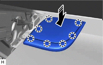
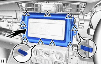
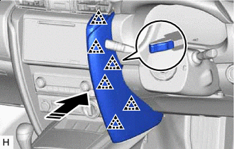
Install in this Direction Attach the claw to install the No. 2 instrument panel speaker panel sub-assembly as shown in the illustration.
-
-
INSTALL NO. 1 INSTRUMENT PANEL SPEAKER PANEL SUB-ASSEMBLY (for 11 Speakers)
-
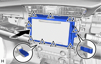
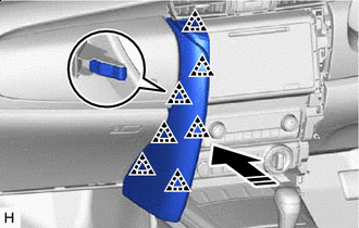
Install in this Direction Attach the claw to install the No. 1 instrument panel speaker panel sub-assembly as shown in the illustration.
-
-
INSTALL FRONT PILLAR GARNISH LH
-
Install in this Direction (1) 
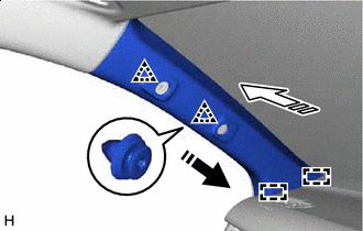
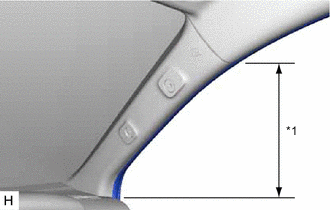
Install in this Direction (2) Attach the guide and clip to install the front pillar garnish LH as shown in the illustration.
-
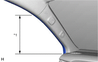
*1 Front Door Opening Trim Weatherstrip LH Connect the front door opening trim weatherstrip LH in the range shown in the illustration.
-
-
INSTALL FRONT PILLAR GARNISH RH
-
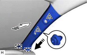
Install in this Direction (1) Install in this Direction (2) Attach the guide and clip to install the front pillar garnish RH as shown in the illustration.
-
*1 Front Door Opening Trim Weatherstrip RH Connect the front door opening trim weatherstrip RH in the range shown in the illustration.
-
-
INSTALL FRONT ASSIST GRIP SUB-ASSEMBLY
Tech Tips
Use the same procedure for both front assist grip sub-assemblies.
-
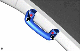
Install the front assist grip sub-assembly with the 2 bolts.
-
Attach the claw to close the assist grip covers.
-
-
INSTALL INSTRUMENT SIDE PANEL LH
-
Connect the connector.
-
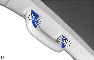
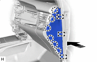
Install in this Direction Attach the guide and claw to install the instrument side panel LH as shown in the illustration.
-
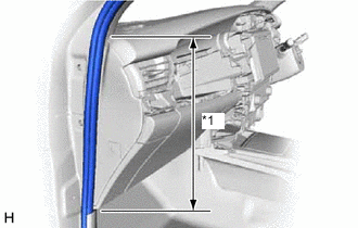
*1 Front Door Opening Trim Weatherstrip LH Connect the front door opening trim weatherstrip LH in the range shown in the illustration.
-
-
INSTALL COWL SIDE TRIM BOARD LH
-
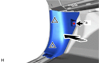
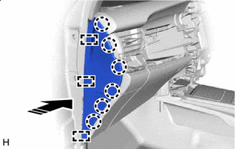
*a Cap Nut Install in this Direction Attach the clip to install the cowl side trim board LH as shown in the illustration.
-
Install the cap nut.
-
-
INSTALL FRONT DOOR SCUFF PLATE LH
-
INSTALL INSTRUMENT SIDE PANEL RH
-
Install in this Direction Attach the guide and claw to install the instrument side panel RH as shown in the illustration.
-
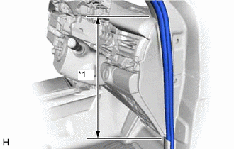
*1 Front Door Opening Trim Weatherstrip RH Connect the front door opening trim weatherstrip RH in the range shown in the illustration.
-
-
INSTALL COWL SIDE TRIM BOARD RH
-
*a Cap Nut Install in this Direction Attach the clip to install the cowl side trim board RH as shown in the illustration.
-
Install the cap nut.
-
-
INSTALL FRONT DOOR SCUFF PLATE RH
-
INSTALL CENTER INSTRUMENT CLUSTER FINISH PANEL SUB-ASSEMBLY
-
for Type A:
-
Install in this Direction Attach the clip to install the center instrument cluster finish panel sub-assembly as shown in the illustration.
-
-
for Type B:
-
Install in this Direction Attach the clip to install the center instrument cluster finish panel sub-assembly as shown in the illustration.
-
-
-
INSTALL NO. 1 INSTRUMENT PANEL BOX DOOR SUB-ASSEMBLY
-
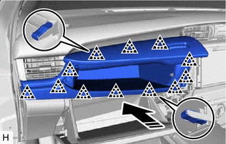
Install in this Direction Attach the clip to install the No. 1 instrument panel box door sub-assembly as shown in the illustration.
-
-
INSTALL COMBINATION METER ASSEMBLY
-
INSTALL INSTRUMENT CLUSTER FINISH PANEL ASSEMBLY
-
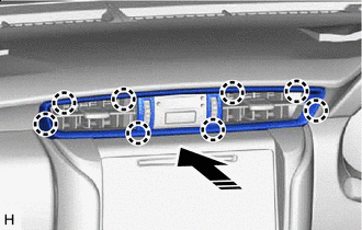
Install in this Direction Attach the clip to install the instrument cluster finish panel assembly as shown in the illustration.
-
-
INSTALL NO. 1 INSTRUMENT PANEL GARNISH SUB-ASSEMBLY
-
Install in this Direction Attach the clip to install the No. 1 instrument panel garnish sub-assembly as shown in the illustration.
-
-
INSTALL NO. 2 INSTRUMENT PANEL GARNISH SUB-ASSEMBLY
-
Install in this Direction Attach the clip to install the No. 2 instrument panel garnish sub-assembly as shown in the illustration.
-
-
INSTALL INSTRUMENT PANEL REGISTER BEZEL GARNISH
-
Install in this Direction Attach the claw to install the instrument panel register bezel garnish as shown in the illustration.
-
-
INSTALL STEERING WHEEL ASSEMBLY
-
CONNECT CABLE TO NEGATIVE BATTERY TERMINAL
Note
When disconnecting the cable, some systems need to be initialized after the cable is reconnected.
-
CHECK SRS WARNING LIGHT