UPPER INSTRUMENT PANEL REMOVAL
CAUTION / NOTICE / HINT
Tech Tips
-
Use the same procedure for RHD and LHD vehicles.
-
The procedure listed below is for RHD vehicles.
The necessary procedures (adjustment, calibration, initialization or registration) that must be performed after parts are removed, installed or replaced during the upper instrument panel removal/installation are shown below.
| Replacement Part or Procedure | Necessary Procedures | Effects / Inoperative when not Performed | Link |
|---|---|---|---|
| Disconnect cable from negative battery terminal | w/ Power Back Door System: Reset back door close position |
Power door lock control system |
CAUTION:
Some of these service operations affect the SRS airbag system. Read the precautionary notices concerning the SRS airbag system before servicing.
PROCEDURE
-
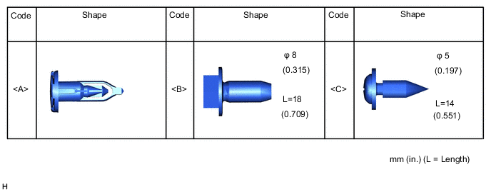
TABLE OF BOLT, SCREW, NUT AND CLIP
Tech Tips
All bolts, screws and clips relevant to installing and removing the instrument panel are shown along with their alphabetic code in the table below.
-
PRECAUTION
Note
After turning the ignition switch off, waiting time may be required before disconnecting the cable from the battery terminal. Therefore, make sure to read the disconnecting the cable from the battery terminal notice before proceeding with work.
-
DISCONNECT CABLE FROM NEGATIVE BATTERY TERMINAL
CAUTION:
Wait at least 90 seconds after disconnecting the cable from the negative (-) battery terminal to disable the SRS system.
Note
When disconnecting the cable, some systems need to be initialized after the cable is reconnected.
-
REMOVE STEERING WHEEL ASSEMBLY
-
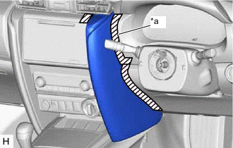
REMOVE INSTRUMENT PANEL REGISTER BEZEL GARNISH
-
*a Protective Tape Put protective tape around the instrument panel register bezel garnish.
-

Place Hands Here 
Remove in this Direction Place your hands at the position shown in the illustration and pull as shown to detach the claw and remove the instrument panel register bezel garnish.
-
-
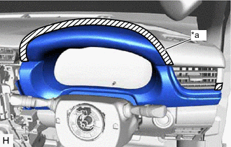
REMOVE NO. 1 INSTRUMENT PANEL GARNISH SUB-ASSEMBLY
-
*a Protective Tape Put protective tape around the No. 1 instrument panel garnish sub-assembly.
-
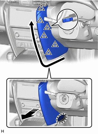
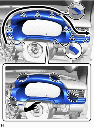
Place Hands Here Remove in this Direction 
Order of Removal Place your hands at the position shown in the illustration and pull as shown to detach the clip and remove the No. 1 instrument panel garnish sub-assembly.
-
-
REMOVE NO. 2 INSTRUMENT PANEL GARNISH SUB-ASSEMBLY
-
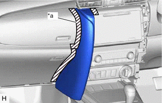
*a Protective Tape Put protective tape around the No. 2 instrument panel garnish sub-assembly.
-
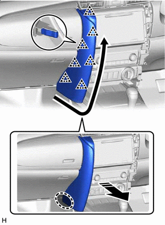
Place Hands Here Remove in this Direction Order of Removal Place your hands at the position shown in the illustration and pull as shown to detach the clip and remove the No. 2 instrument panel garnish sub-assembly.
-
-
REMOVE INSTRUMENT CLUSTER FINISH PANEL ASSEMBLY
-
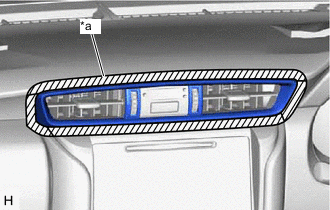
*a Protective Tape Put protective tape around the instrument cluster finish panel assembly.
-
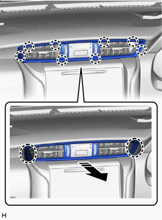
Place Hands Here Remove in this Direction Order of Removal Place your hands at the position shown in the illustration and pull as shown to detach the clip and remove the instrument cluster finish panel assembly.
-
-
REMOVE COMBINATION METER ASSEMBLY
-
REMOVE NO. 1 INSTRUMENT PANEL BOX DOOR SUB-ASSEMBLY
-
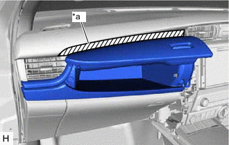
*a Protective Tape Put protective tape around the No. 1 instrument panel box door sub-assembly.
-
Open the glove compartment door assembly.
-
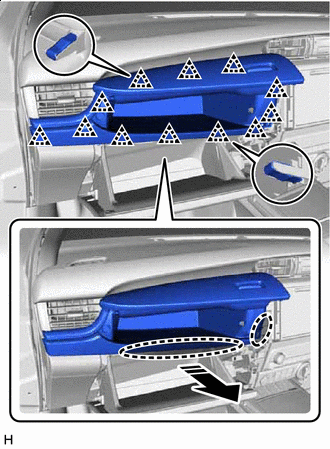
Place Hands Here Remove in this Direction Place your hands at the position shown in the illustration and pull as shown to detach the clip and remove the No. 1 instrument panel box door sub-assembly.
-
-
REMOVE CENTER INSTRUMENT CLUSTER FINISH PANEL SUB-ASSEMBLY
-
for Type A:
-
Place Hands Here Remove in this Direction Place your hands at the position shown in the illustration and pull as shown to detach the clip and remove the center instrument cluster finish panel sub-assembly.
-
-
for Type B:
-
Place Hands Here Remove in this Direction Place your hands at the position shown in the illustration and pull as shown to detach the clip and remove the center instrument cluster finish panel sub-assembly.
-
-
-
REMOVE FRONT DOOR SCUFF PLATE RH
-
REMOVE COWL SIDE TRIM BOARD RH
*a Cap Nut Place Hands Here Remove in this Direction
-
Remove the cap nut.
-
Place your hands at the position shown in the illustration and pull as shown to detach the clip and remove the cowl side trim board RH.
-
-
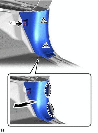
REMOVE INSTRUMENT SIDE PANEL RH
-
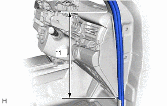
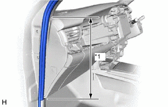
*1 Front Door Opening Trim Weatherstrip RH Disconnect the front door opening trim weatherstrip RH in the range shown in the illustration.
-
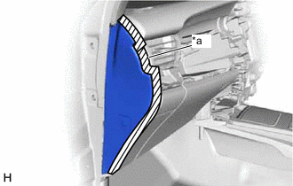
*a Protective Tape Put protective tape around the instrument side panel RH.
-
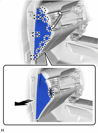
Insert Moulding Remover A Here Remove in this Direction Insert moulding remover A at the position shown in the illustration and pull as shown to detach the claw and guide and remove the instrument side panel RH.
-
-
REMOVE FRONT DOOR SCUFF PLATE LH
-
REMOVE COWL SIDE TRIM BOARD LH
-
*a Cap Nut Place Hands Here Remove in this Direction Remove the cap nut.
-
Place your hands at the position shown in the illustration and pull as shown to detach the clip and remove the cowl side trim board LH.
-
-
REMOVE INSTRUMENT SIDE PANEL LH
-
*1 Front Door Opening Trim Weatherstrip LH Disconnect the front door opening trim weatherstrip LH in the range shown in the illustration.
-
*a Protective Tape Put protective tape around the instrument side panel LH.
-
Insert Moulding Remover A Here Remove in this Direction Insert moulding remover A at the position shown in the illustration and pull as shown to detach the claw and guide.
-
Disconnect the connector and remove the instrument side panel LH.
-
-
REMOVE FRONT ASSIST GRIP SUB-ASSEMBLY
Tech Tips
Use the same procedure for both front assist grip assemblies.
-
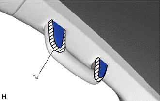
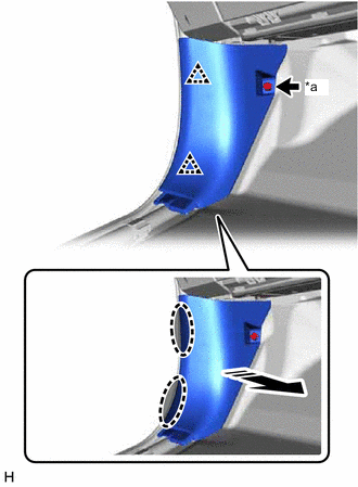
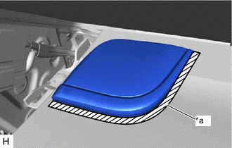
*a Protective Tape Put protective tape around the assist grip covers.
-
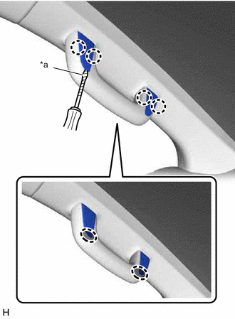
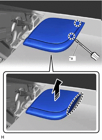
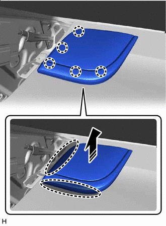
*a Protective Tape Insert Thin-bladed Screwdriver Here Insert a thin-bladed screwdriver at the position shown in the illustration and detach the claw and open the assist grip covers.
Tech Tips
Tape the thin-bladed screwdriver tip before use.
-
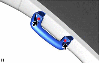
Remove the 2 bolts and front assist grip sub-assembly.
-
-
REMOVE FRONT PILLAR GARNISH LH
-
*a Protective Tape Put protective tape around the front pillar garnish LH.
-
*1 Front Door Opening Trim Weatherstrip LH Disconnect the front door opening trim weatherstrip LH in the range shown in the illustration.
-
Place Hands Here Remove in this Direction (1) 
Remove in this Direction (2) Place your hands at the position shown in the illustration and pull as shown to detach the clip and guide and remove the front pillar garnish LH.
-
w/ Curtain Shield Airbag:
Protect the curtain shield airbag assembly LH.
-
*a Protective Cover *b Adhesive Tape Completely cover the curtain shield airbag assembly LH with a cloth or nylon sheet and secure the ends of the cover with adhesive tape as shown in the illustration.
Note
Cover the curtain shield airbag assembly LH with a protective cover as soon as the front pillar garnish LH is removed.
-
-
-
REMOVE FRONT PILLAR GARNISH RH
-
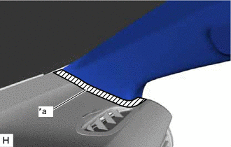
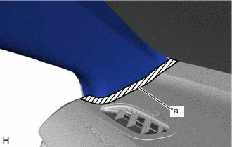
*a Protective Tape Put protective tape around the front pillar garnish RH.
-
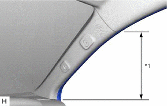
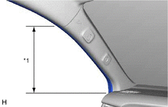
*1 Front Door Opening Trim Weatherstrip RH Disconnect the front door opening trim weatherstrip RH in the range shown in the illustration.
-
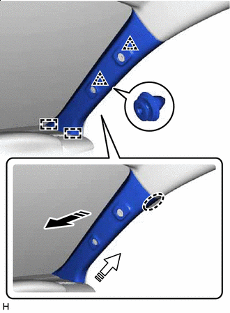
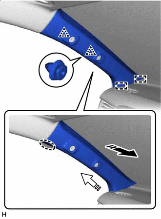
Place Hands Here Remove in this Direction (1) Remove in this Direction (2) Place your hands at the position shown in the illustration and pull as shown to detach the clip and guide and remove the front pillar garnish RH.
-
w/ Curtain Shield Airbag:
Protect the curtain shield airbag assembly RH.
-
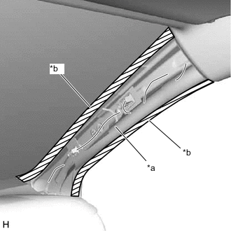
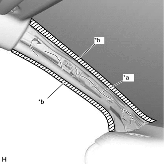
*a Protective Cover *b Adhesive Tape Completely cover the curtain shield airbag assembly RH with a cloth or nylon sheet and secure the ends of the cover with adhesive tape as shown in the illustration.
Note
Cover the curtain shield airbag assembly RH with a protective cover as soon as the front pillar garnish RH is removed.
-
-
-
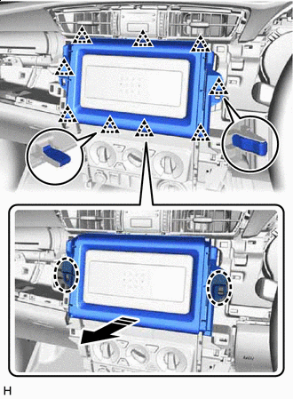
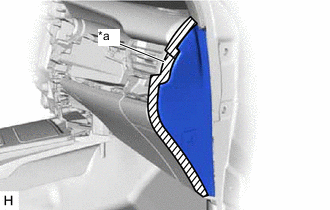
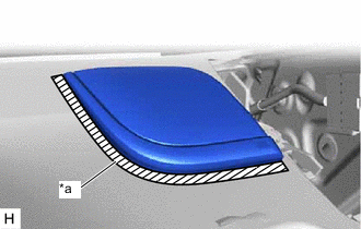
REMOVE NO. 2 INSTRUMENT PANEL SPEAKER PANEL SUB-ASSEMBLY (for 11 Speakers)
-
*a Protective Tape Put protective tape around the No. 2 instrument panel speaker panel sub-assembly.
-
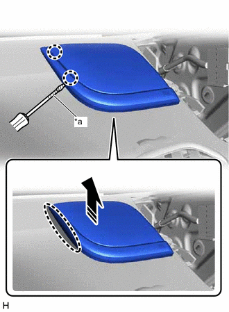
*a Protective Tape Insert Screwdriver Here Remove in this Direction Insert a screwdriver at the position shown in the illustration and detach the claw.
Tech Tips
Tape the screwdriver tip before use.
-
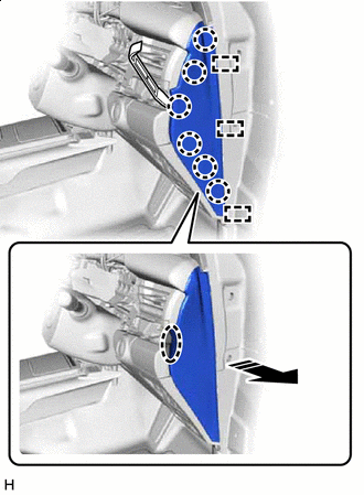
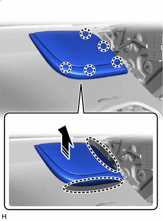
Place Hands Here Remove in this Direction Place your hand in the gap to detach the claw and remove the No. 2 instrument panel speaker panel sub-assembly as shown in the illustration.
-
-
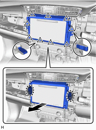
REMOVE NO. 1 INSTRUMENT PANEL SPEAKER PANEL SUB-ASSEMBLY (for 11 Speakers)
-
*a Protective Tape Put protective tape around the No. 1 instrument panel speaker panel sub-assembly.
-
*a Protective Tape Insert Screwdriver Here Remove in this Direction Insert a screwdriver at the position shown in the illustration and detach the claw.
Tech Tips
Tape the screwdriver tip before use.
-
Place Hands Here Remove in this Direction Place your hand in the gap to detach the claw and remove the No. 1 instrument panel speaker panel sub-assembly as shown in the illustration.
-
-
REMOVE FRONT NO. 3 SPEAKER ASSEMBLY (for 11 Speakers)
-
REMOVE FRONT NO. 1 SPEAKER BRACKET (for 11 Speakers)
-
REMOVE UPPER INSTRUMENT PANEL SUB-ASSEMBLY
-
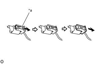
*a Lock Slider Pull and slide the lock slider as shown to release the connector lock and disconnect the passenger airbag connector.
Note
When handling the passenger airbag connector, take care not to damage the airbag wire harness.
-
Disconnect the connector and detach the clamp.
-
Remove the 2 clips <A>.
-
Remove the passenger airbag installation bolt <B>.
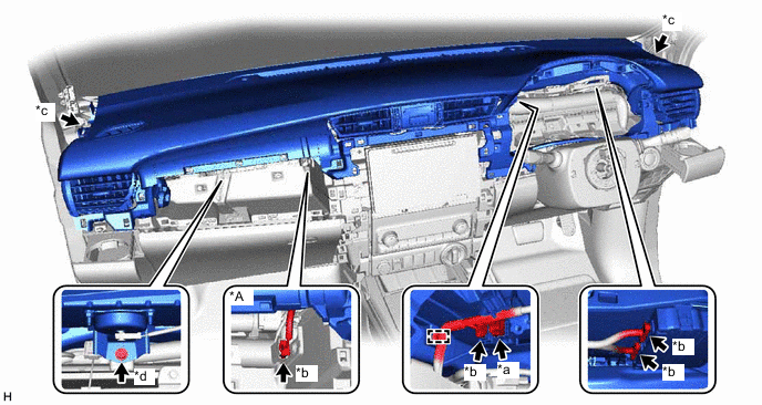
*A w/ Navigation System - - *a Passenger Airbag Connector *b Connector *c Clip <A> *d Passenger Airbag Installation Bolt <B> -
Place your hands at the position shown in the illustration and pull as shown to detach the clip.
-
Detach the guide and remove the upper instrument panel sub-assembly.
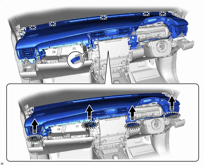
Place Hands Here Remove in this Direction
-