POWER POINT SOCKET(for Front Side) INSTALLATION
PROCEDURE
-
INSTALL NO. 1 POWER OUTLET SOCKET COVER
-
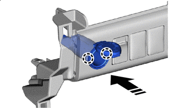

Install in this Direction Attach the claw to install the No. 1 power outlet socket cover as shown in the illustration.
-
-
INSTALL NO. 1 POWER OUTLET SOCKET ASSEMBLY
-
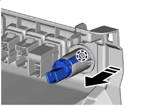
Install in this Direction Attach the claw to install the No. 1 power outlet socket assembly as shown in the illustration.
-
-
INSTALL LOWER INSTRUMENT COVER SUB-ASSEMBLY
-
INSTALL AIR CONDITIONING CONTROL ASSEMBLY (for Automatic Air Conditioning System)
-
INSTALL INTEGRATION PANEL SUB-ASSEMBLY (for Manual Air Conditioning System)
-
INSTALL CONTROL KNOB SUB-ASSEMBLY (for Manual Air Conditioning System)
-
INSTALL NAVIGATION RECEIVER ASSEMBLY (w/ Navigation System)
-
INSTALL RADIO AND DISPLAY RECEIVER ASSEMBLY (w/o Navigation System)
-
INSTALL CENTER INSTRUMENT CLUSTER FINISH PANEL SUB-ASSEMBLY
-
INSTALL NO. 1 INSTRUMENT PANEL GARNISH SUB-ASSEMBLY
-
INSTALL NO. 2 INSTRUMENT PANEL GARNISH SUB-ASSEMBLY
-
INSTALL INSTRUMENT PANEL REGISTER BEZEL GARNISH