POWER POINT SOCKET(for Front Side) REMOVAL
PROCEDURE
-
REMOVE INSTRUMENT PANEL REGISTER BEZEL GARNISH
-
REMOVE NO. 1 INSTRUMENT PANEL GARNISH SUB-ASSEMBLY
-
REMOVE NO. 2 INSTRUMENT PANEL GARNISH SUB-ASSEMBLY
-
REMOVE CENTER INSTRUMENT CLUSTER FINISH PANEL SUB-ASSEMBLY
-
REMOVE RADIO AND DISPLAY RECEIVER ASSEMBLY (w/o Navigation System)
-
REMOVE NAVIGATION RECEIVER ASSEMBLY (w/ Navigation System)
-
REMOVE CONTROL KNOB SUB-ASSEMBLY (for Manual Air Conditioning System)
-
REMOVE INTEGRATION PANEL SUB-ASSEMBLY (for Manual Air Conditioning System)
-
REMOVE AIR CONDITIONING CONTROL ASSEMBLY (for Automatic Air Conditioning System)
-
REMOVE LOWER INSTRUMENT COVER SUB-ASSEMBLY
-
REMOVE NO. 1 POWER OUTLET SOCKET ASSEMBLY
-
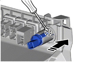

Protective Tape 
Remove in this Direction Using a thin-bladed screwdriver, detach the claw, and remove the No. 1 power outlet socket assembly as shown in the illustration.
Tech Tips
Tape the thin-bladed screwdriver tip before use.
-
-
REMOVE NO. 1 POWER OUTLET SOCKET COVER
-
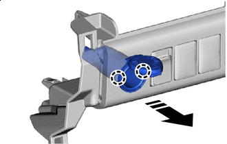
Remove in this Direction Detach the claw and remove the No. 1 power outlet socket cover as shown in the illustration.
-