HEATER SWITCH INSPECTION
PROCEDURE
-
INSPECT IDLE UP SWITCH
-
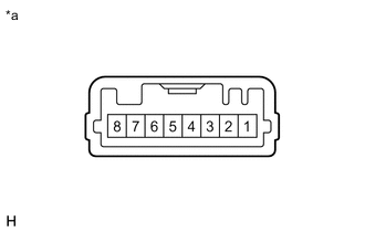
*a Component without harness connected
(Idle Up Switch)
Measure the resistance according to the value(s) in the table below.
Standard Resistance Tester Connection Switch Condition Specified Condition 3 - 6 Idle up switch ON position Below 10 Ω Idle up switch OFF position 10 kΩ or higher If the result is not as specified, replace the idle up switch.
-
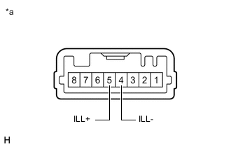
*a Component without harness connected
(Idle Up Switch)
Check that the illumination.
-
Apply battery voltage to the connector terminal and check the illumination.
OK Measurement Condition Specified Condition Battery positive (+) → 5 (ILL+)
Battery negative (-) → 4 (ILL-)
Idle up switch illuminates If the result is not as specified, replace the idle up switch.
-
-
-
INSPECT HEATER SWITCH ASSEMBLY
-
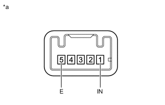
*a Component without harness connected
(Heater Switch Assembly)
Measure the resistance according to the value(s) in the table below.
Standard Resistance Tester Connection Switch Condition Specified Condition 1 (IN) - 5 (E) Heater switch assembly ON position Below 10 Ω Heater switch assembly OFF position 10 kΩ or higher If the result is not as specified, replace the heater switch assembly.
-
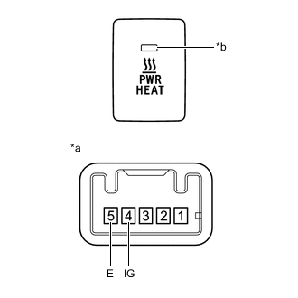
*a Component without harness connected
(Heater Switch Assembly)
*b Indicator Check that the Indicator.
-
Apply battery voltage to the connector terminal and check the Indicator.
OK Measurement Condition Switch Condition Specified Condition Battery positive (+) → 4 (IG)
Battery negative (-) → 5 (E)
Heater switch assembly ON position Indicator illuminates If the result is not as specified, replace the heater switch assembly.
-
-
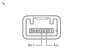
*a Component without harness connected
(Heater Switch Assembly)
Check that the illumination.
-
Apply battery voltage to the connector terminal and check the illumination.
OK Measurement Condition Specified Condition Battery positive (+) → 3 (ILL+)
Battery negative (-) → 2 (ILL-)
Heater switch assembly illuminates If the result is not as specified, replace the heater switch assembly.
-
-