PRESSURE SWITCH ON-VEHICLE INSPECTION
PROCEDURE
-
INSPECT NO. 1 PRESSURE SWITCH (w/o Condenser Fan)
-
Disconnect the connector.
-
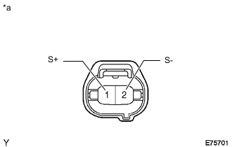
*a Front view of wire harness connector
(No. 1 Pressure Switch)
Using a service wire, connect terminals 1 (S+) and 2 (S-) of the No. 1 pressure switch connector on the vehicle wire harness side.
-
Start the engine.
-
Turn the A/C switch on and check that the magnet clutch turns on.
-
Check that the magnet clutch turns off when disconnecting terminals 1 (S+) and 2 (S-).
OK Measurement Condition Specified Condition Terminals 1 (S+) and 2 (S-) connected Magnet clutch turns on Terminals 1 (S+) and 2 (S-) disconnected Magnet clutch turns off If the result is not as specified, replace the No. 1 pressure switch.
-
-
INSPECT NO. 1 PRESSURE SWITCH (w/ Condenser Fan)
-
Disconnect the connector.
-
Start the engine.
-
Turn the A/C switch on and check that the magnet clutch turns on.
-
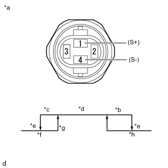
*a Component without harness connected
(No. 1 Pressure Switch)
*b High Pressure Side *c Low Pressure Side *d ON (Continuity) *e OFF (No Continuity) *f 176 to 216 kPa (1.8 to 2.2 kgf/cm2, 26 to 31 psi)
*g 196 to 250 kPa (2.0 to 2.5 kgf/cm2, 28 to 36 psi)
*h 3140 to 3340 kPa (32.0 to 34.1 kgf/cm2, 455 to 484 psi)
High Pressure Side, Low Pressure Side (Magnet Clutch Control):
Measure the resistance according to the value(s) in the table below.
OK Measurement Condition Refrigerant Volume Specified Condition 1 (S+) - 4 (S-) See the graph Below 1 Ω 1 (S+) - 4 (S-) 10 kΩ or higher If the result is not as specified, replace the No. 1 pressure switch.
-
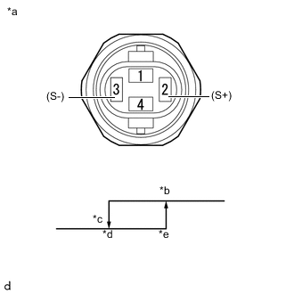
*a Component without harness connected
(No. 1 Pressure Switch)
*b ON (Continuity) *c OFF (No Continuity) *d 111 to 135 kPa (1.1 to 1.4 kgf/cm2, 16 to 20 psi)
*e 144 to 160 kPa (1.5 to 1.6 kgf/cm2, 21 to 23 psi)
Middle Pressure Side (Condenser Fan Control):
Measure the resistance according to the value(s) in the table below.
OK Measurement Condition Refrigerant Volume Specified Condition 2 (S+) - 3 (S-) See the graph Below 1 Ω 2 (S+) - 3 (S-) 10 kΩ or higher If the result is not as specified, replace the No. 1 pressure switch.
-