AIR CONDITIONING PANEL(for Manual Air Conditioning System) INSPECTION
PROCEDURE
-
INSPECT AIR CONDITIONING CONTROL ASSEMBLY
-
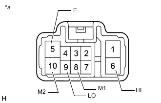
*a Component without harness connected
(Air Conditioning Control Assembly)
Check the blower switch resistance.
-
Measure the resistance according to the value(s) in the table below.
Standard Resistance Tester Connection Condition Specified Condition 9 (LO), 6 (HI), 8 (M1) or 10 (M2) - 5 (E) OFF 10 kΩ or higher 9 (LO) - 5 (E) Blower Switch 1 Below 1 Ω 9 (LO) or 8 (M1) - 5 (E) Blower Switch 1 - 2 Below 1 Ω 9 (LO) or 8 (M1) - 5 (E) Blower Switch 2 Below 1 Ω 9 (LO), 8 (M1) or 10 (M2) - 5 (E) Blower Switch 2 - 3 Below 1 Ω 9 (LO) or 10 (M2) - 5 (E) Blower Switch 3 Below 1 Ω 9 (LO), 6 (HI) or 10 (M2) - 5 (E) Blower Switch 3 - 4 Below 1 Ω 9 (LO) or 6 (HI) - 5 (E) Blower Switch 4 Below 1 Ω If the result is not as specified, replace the air conditioning control assembly.
-
-
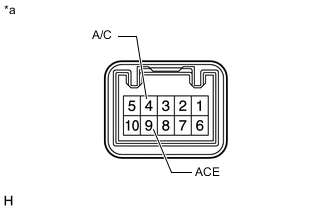
*a Component without harness connected
(Air Conditioning Control Assembly)
Check the A/C switch resistance.
-
Measure the resistance according to the value(s) in the table below.
Standard Resistance Tester Connection Condition Specified Condition 9 (ACE) - 4 (A/C) OFF 10 kΩ or higher 9 (ACE) - 4 (A/C) ON Below 1 Ω If the result is not as specified, replace the air conditioning control assembly.
-
-
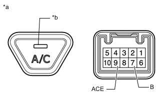
*a Component without harness connected
(Air Conditioning Control Assembly (A/C Switch))
*b Indicator Check that the A/C switch LED illuminates.
-
Apply battery voltage to the air conditioning control assembly (A/C switch) and check that the LED illuminates.
OK Measurement Condition Condition Specified Condition Battery positive (+) → 7 (B)
Battery negative (-) → 9 (ACE)
A/C Switch ON Indicator illuminates If the result is not as specified, replace the air conditioning control assembly.
-
-
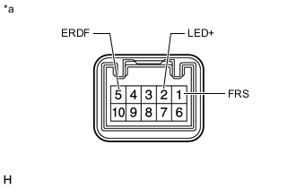
*a Component without harness connected
(Air Conditioning Control Assembly)
Check the recirculation/fresh switch resistance.
-
Measure the resistance according to the value(s) in the table below.
Standard Resistance Tester Connection Condition Specified Condition 1 (FRS) - 5 (ERDF) OFF Below 1 Ω 2 (LED+) - 5 (ERDF) OFF 10 kΩ or higher 2 (LED+) - 5 (ERDF) ON Below 1 Ω 1 (FRS) - 5 (ERDF) ON 10 kΩ or higher If the result is not as specified, replace the air conditioning control assembly.
-
-
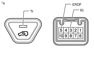
*a Component without harness connected
(Air Conditioning Control Assembly (recirculation/fresh switch))
*b Indicator Check that the recirculation/fresh switch LED illuminates.
-
Apply battery voltage to the air conditioning control assembly (recirculation/fresh switch) and check that the LED illuminates.
OK Measurement Condition Switch Position Specified Condition Battery positive (+) → 3 (IG)
Battery negative (-) → 5 (ERDF)
Recirculation/fresh switch: ON Indicator illuminates If the result is not as specified, replace the air conditioning control assembly.
-
-