VISCOUS HEATER INSTALLATION
PROCEDURE
-
INSTALL VISCOUS HEATER WITH MAGNET CLUTCH ASSEMBLY
-
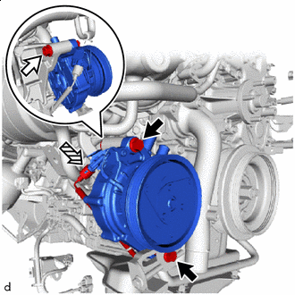

Bolt 
Nut 
Connector Temporarily install the viscous heater with magnet clutch assembly with the 2 bolts and nut.
-
Connect the connector.
-
-
CONNECT HEATER WATER HOSE INLET B
-
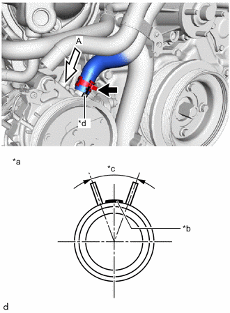
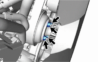
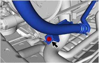
*a View A *b Paint Marking (Red) *c Clip Installation Angle (40°) *d Rib Align the rib of the viscous heater with magnet clutch assembly with the marking (red). Connect the heater water hose inlet B and install the hose clip within the range shown in the illustration.
Note
Do not apply excessive force to the heater water hose inlet B.
-
-
CONNECT HEATER WATER HOSE OUTLET B
-
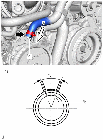
*a View A *b Paint Marking (Red) *c Clip Installation Angle (40°) *d Rib Align the rib of the viscous heater with magnet clutch assembly with the marking (red). Connect the heater water hose outlet B and install the hose clip within the range shown in the illustration.
Note
Do not apply excessive force to the heater water hose outlet B.
-
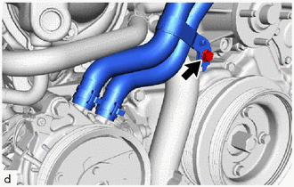
Install the bolt.
- Torque:
- 5.4 N*m { 55 kgf*cm, 48 in.*lbf }
-
-
INSTALL FAN SHROUD
-
Install the fan pulley to the engine water pump assembly.
-
Place the fan shroud together with the fan with fluid coupling assembly between the engine and radiator assembly.
Note
Do not allow the radiator assembly to interfere with other parts.
-
Temporarily install the fan with fluid coupling assembly to the engine water pump assembly with the 4 nuts.
Note
-
Make sure to match the paint mark colors on the fan with fluid coupling assembly with the stud bolts of the same color on the engine water pump assembly.
-
When installing the fan and generator V belt, make sure to securely tighten the nuts of the fan with fluid coupling assembly so that the fan pulley is properly aligned.
-
-
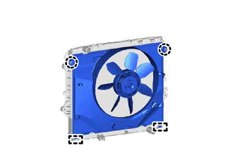
Attach the guide and claw to install the fan shroud to the radiator assembly.
-
Install the fan and generator V belt.
-
Tighten the 4 nuts holding the fan with fluid coupling assembly.
- Torque:
- 23 N*m { 235 kgf*cm, 17 ft.*lbf }
-
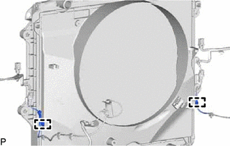
Attach the clamp.
-
Attach the clamp.
-
-
INSTALL VISCOUS HEATER V BELT
-
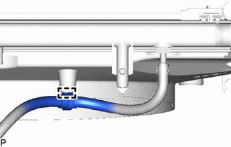
CONNECT SUCTION HOSE SUB-ASSEMBLY
-
Connect the suction hose sub-assembly.
- Torque:
- 5.4 N*m { 55 kgf*cm, 48 in.*lbf }
-
-
INSTALL RADIATOR RESERVOIR
-
INSTALL NO. 1 OIL RESERVOIR BRACKET
-
CONNECT VANE PUMP OIL RESERVOIR ASSEMBLY
-
INSTALL NO. 1 RADIATOR HOSE
-
INSTALL NO. 2 AIR TUBE
-
INSTALL NO. 4 AIR HOSE
-
ADD ENGINE COOLANT
-
INSPECT FOR COOLANT LEAK
-
INSTALL RADIATOR SIDE DEFLECTOR LH
-
INSTALL NO. 1 ENGINE UNDER COVER ASSEMBLY
-
INSTALL NO. 1 ENGINE COVER SUB-ASSEMBLY