COMPRESSOR(for 1KD-FTV, 2KD-FTV) INSTALLATION

PROCEDURE
-
ADJUST COMPRESSOR OIL
-
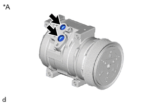
*A for Type A 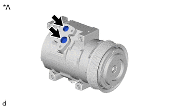
*A for Type B When replacing the compressor assembly with magnet clutch with a new one, gradually discharge the refrigerant gas from the service valve, and drain the following amount of oil from the new compressor assembly with magnet clutch before installation.
Standard for Type A (Oil capacity inside the new compressor assembly with magnet clutch: 200 to 215 cc (6.76 to 7.27 fl.oz)) - (Remaining oil amount in the removed compressor assembly with magnet clutch) = (Oil amount to be removed from the new compressor) for Type B (Oil capacity inside the new compressor assembly with magnet clutch: 200 to 215 cc (6.76 to 7.27 fl.oz)) - (Remaining oil amount in the removed compressor assembly with magnet clutch) = (Oil amount to be removed from the new compressor) Note
-
If a new compressor assembly with magnet clutch is installed without removing some oil, there will be too much oil in the system due to the oil remaining in the pipes of the vehicle. Excessive oil in the system prevents heat exchange in the refrigeration cycle and causes ineffective cooling.
-
If the amount of oil remaining in the old compressor assembly with magnet clutch is too small, check the air conditioning system for oil leaks.
-
Be sure to use ND-OIL 8 or equivalent compressor oil. If any compressor oil other than ND-OIL 8 is used, compressor assembly with magnet clutch insulation performance may decrease, resulting in a leak of electric power.
-
-
-
INSTALL COMPRESSOR ASSEMBLY WITH MAGNET CLUTCH
-
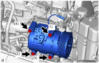
for Type A:
Tighten the 4 bolts in the order shown in the illustration to install the compressor assembly with magnet clutch.
- Torque:
- 24.5 N*m { 250 kgf*cm, 18 ft.*lbf }
-
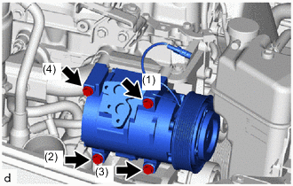
for Type B:
Tighten the 4 bolts in the order shown in the illustration to install the compressor assembly with magnet clutch.
- Torque:
- 24.5 N*m { 250 kgf*cm, 18 ft.*lbf }
-
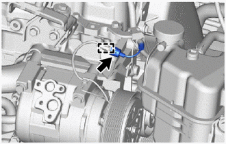
for Type A:
-
Connect the connector.
-
Attach the clamp.
-
-
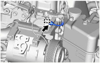
for Type B:
-
Connect the connector.
-
Attach the clamp.
-
-
-
CONNECT SUCTION HOSE SUB-ASSEMBLY
-
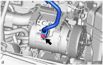
for Type A:
-
Remove the vinyl tape from the suction hose sub-assembly and compressor assembly with magnet clutch.
-
Sufficiently apply compressor oil to a new O-ring and the fitting surface of the compressor assembly with magnet clutch.
Compressor Oil ND-OIL 8 or equivalent -
Install the O-ring to the suction hose sub-assembly.
Note
Keep the O-ring and O-ring fitting surfaces free of foreign matter.
-
Connect the suction hose sub-assembly to the compressor assembly with magnet clutch with the bolt.
- Torque:
- 9.8 N*m { 100 kgf*cm, 87 in.*lbf }
-
-
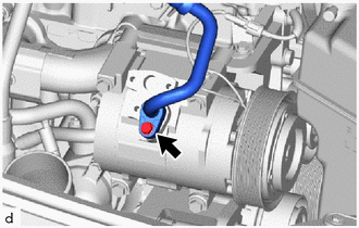
for Type B:
-
Remove the vinyl tape from the suction hose sub-assembly and compressor assembly with magnet clutch.
-
Sufficiently apply compressor oil to a new O-ring and the fitting surface of the compressor assembly with magnet clutch.
Compressor Oil ND-OIL 8 or equivalent -
Install the O-ring to the suction hose sub-assembly.
Note
Keep the O-ring and O-ring fitting surfaces free of foreign matter.
-
Connect the suction hose sub-assembly to the compressor assembly with magnet clutch with the bolt.
- Torque:
- 9.8 N*m { 100 kgf*cm, 87 in.*lbf }
-
-
-
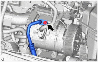
CONNECT NO. 1 COOLER REFRIGERANT DISCHARGE HOSE
-
for Type A:
-
Remove the vinyl tape from the No. 1 cooler refrigerant discharge hose and compressor assembly with magnet clutch.
-
Sufficiently apply compressor oil to a new O-ring and the fitting surface of the compressor assembly with magnet clutch.
Compressor Oil ND-OIL 8 or equivalent -
Install the O-ring to the No. 1 cooler refrigerant discharge hose.
Note
Keep the O-ring and O-ring fitting surfaces free of foreign matter.
-
Connect the No. 1 cooler refrigerant discharge hose to the compressor assembly with magnet clutch with the bolt.
- Torque:
- 9.8 N*m { 100 kgf*cm, 87 in.*lbf }
-
-
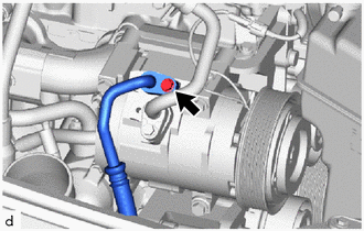
for Type B:
-
Remove the vinyl tape from the No. 1 cooler refrigerant discharge hose and compressor assembly with magnet clutch.
-
Sufficiently apply compressor oil to a new O-ring and the fitting surface of the compressor assembly with magnet clutch.
Compressor Oil ND-OIL 8 or equivalent -
Install the O-ring to the No. 1 cooler refrigerant discharge hose.
Note
Keep the O-ring and O-ring fitting surfaces free of foreign matter.
-
Connect the No. 1 cooler refrigerant discharge hose to the compressor assembly with magnet clutch with the bolt.
- Torque:
- 9.8 N*m { 100 kgf*cm, 87 in.*lbf }
-
-
-
INSTALL FAN AND GENERATOR V BELT
-
for 1KD-FTV:
-
for 2KD-FTV:
-
-
INSTALL NO. 1 ENGINE COVER SUB-ASSEMBLY (w/ Intercooler)
-
CHARGE AIR CONDITIONING SYSTEM WITH REFRIGERANT
-
WARM UP ENGINE
-
INSPECT FOR REFRIGERANT LEAK