FRONT AIR CONDITIONING UNIT REASSEMBLY
PROCEDURE
-
INSTALL NO. 1 COOLER THERMISTOR
-
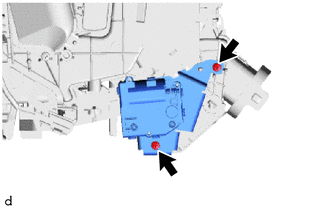
INSTALL NO. 1 COOLER EVAPORATOR SUB-ASSEMBLY
-
Install the No. 1 cooler evaporator sub-assembly together with the No. 1 cooler thermistor to the upper heater case.
-
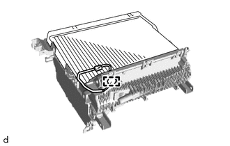
Connect the connector clamp to the upper heater case.
-
Attach the claw to install the upper heater case to the lower heater case.
-
Install the 2 screws.
-
-
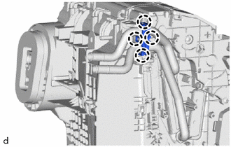
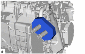
INSTALL COOLER EXPANSION VALVE
-
Sufficiently apply compressor oil to 2 new O-rings and the fitting surface of the No. 1 cooler evaporator sub-assembly.
Compressor Oil ND-OIL 8 or equivalent -
Install the 2 O-rings to the No. 1 cooler evaporator sub-assembly.
Note
Keep the O-rings and O-ring fitting surfaces free of foreign matter.
-
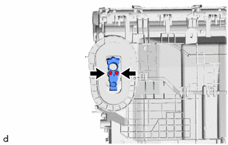
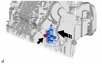
Using a 4 mm hexagon socket wrench, install the cooler expansion valve with the 2 bolts.
- Torque:
- 3.5 N*m { 36 kgf*cm, 31 in.*lbf }
-
-
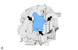
INSTALL HEATER RADIATOR UNIT SUB-ASSEMBLY
-
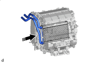

Install in this Direction Install the heater radiator unit sub-assembly as shown in the illustration.
-
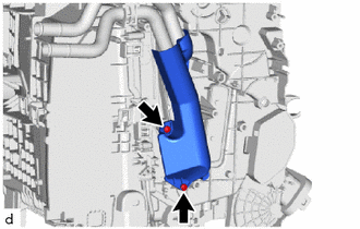
Install the heater radiator cover with the 2 screws.
-
Attach the claw to install the heater clamp.
-
Install the packing.
-
-
INSTALL NO. 2 AIR CONDITIONING RADIATOR DAMPER SERVO SUB-ASSEMBLY (for Automatic Air Conditioning System)
-
Attach the arm of the No. 2 air conditioning radiator damper servo sub-assembly to the link of the air conditioner radiator assembly as shown in the illustration.
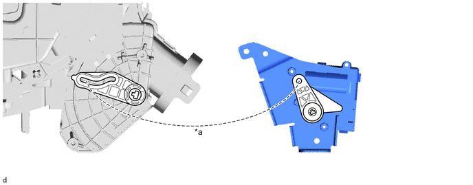
*a Align as shown - - -
Install the No. 2 air conditioning radiator damper servo sub-assembly with the 2 screws.
-
-
INSTALL NO. 1 AIR CONDITIONING RADIATOR DAMPER SERVO SUB-ASSEMBLY (for Automatic Air Conditioning System)
-
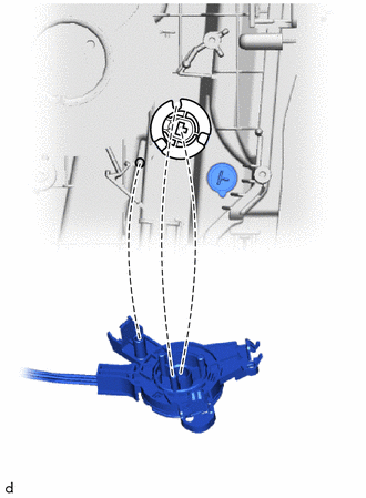
Align each gear on the air conditioning radiator assembly side as shown in the illustration, and then check that the gears of the No. 1 air conditioning radiator damper servo sub-assembly are aligned as shown in the illustration.
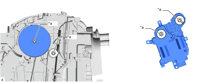
*a Align as shown - - -
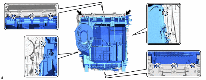
Install the No. 1 air conditioning radiator damper servo sub-assembly with the 3 screws.
-
-
INSTALL DEFROSTER DAMPER CONTROL CABLE SUB-ASSEMBLY (for Manual Air Conditioning System)
-
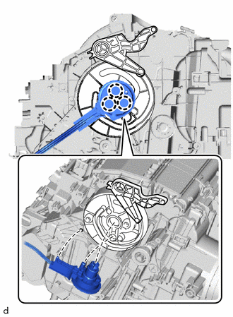
Attach the arm of the defroster damper control cable sub-assembly to the link of the blower assembly as shown in the illustration.
-
Attach the claw to install the defroster damper control cable sub-assembly.
-
-
INSTALL AIR MIX DAMPER CONTROL CABLE SUB-ASSEMBLY (for Manual Air Conditioning System)
-
Attach the arm of the air mix damper control cable sub-assembly to the link of the blower assembly as shown in the illustration.
-
Attach the claw to install the air mix damper control cable sub-assembly.
-
-
INSTALL AIR CONDITIONING AMPLIFIER ASSEMBLY
-
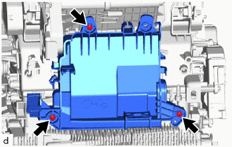
Install the air conditioning amplifier bracket with the 3 screws.
-
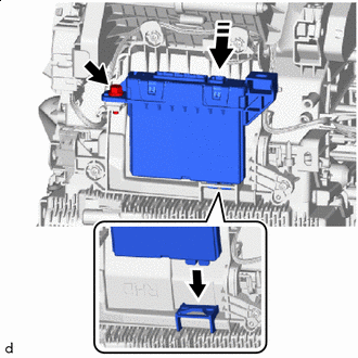
Install in this Direction for Automatic Air Conditioning System:
Install the air conditioning amplifier assembly with the bolt.
- Torque:
- 6.0 N*m { 61 kgf*cm, 53 in.*lbf }
-
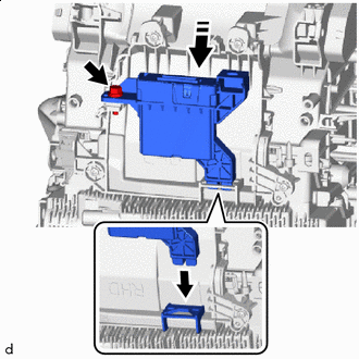
Install in this Direction for Manual Air Conditioning System:
Install the air conditioning amplifier assembly with the bolt.
- Torque:
- 6.0 N*m { 61 kgf*cm, 53 in.*lbf }
-
-
INSTALL AIR CONDITIONING HARNESS ASSEMBLY (for Automatic Air Conditioning System)
-
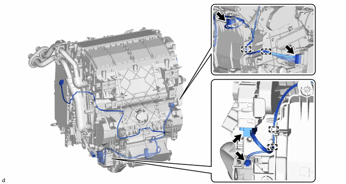
Attach the clamp to install the air conditioning harness assembly.
-
Connect the 4 connectors.
-
-
INSTALL AIR CONDITIONING DUCT SUB-ASSEMBLY (for Automatic Air Conditioning System)
-
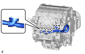
Attach the claw and clamp to install the air conditioning duct sub-assembly.
-
-
INSTALL BLOWER ASSEMBLY
-
INSTALL QUICK HEATER ASSEMBLY (w/ PTC Heater)
-
Install in this Direction Install the quick heater assembly with the screw.
-
-
INSTALL HEATER COVER (w/o PTC Heater)
-
Install in this Direction Install the heater cover with the screw.
-