FRONT AIR CONDITIONING UNIT REMOVAL
CAUTION / NOTICE / HINT
The necessary procedures (adjustment, calibration, initialization or registration) that must be performed after parts are removed, installed or replaced during the front air conditioning unit removal/installation are shown below.
| Replacement Part or Procedure | Necessary Procedures | Effect or Inoperative Function when Necessary Procedure is not Performed | Link |
|---|---|---|---|
| Disconnect cable from negative battery terminal |
w/ Power Back Door System: |
Power back door system |
CAUTION:
Some of these service operations affect the SRS airbag system. Read the precautionary notices concerning the SRS airbag system before servicing.
Tech Tips
-
Use the same procedure for RHD and LHD vehicles.
-
The procedure listed below is for RHD vehicles.
PROCEDURE
-
RECOVER REFRIGERANT FROM REFRIGERATION SYSTEM
-
DRAIN ENGINE COOLANT
-
for 1GR-FE:
-
for 1GD-FTV:
-
for 2GD-FTV:
-
for 2TR-FE:
-
for 5L-E:
-
-
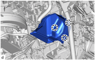
REMOVE NO. 2 WIRING HARNESS PROTECTOR (for GD Series Engine, LHD)
-
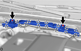
Remove the 2 nuts.
-
Detach the claw and remove the No. 2 wiring harness protector.
-
-
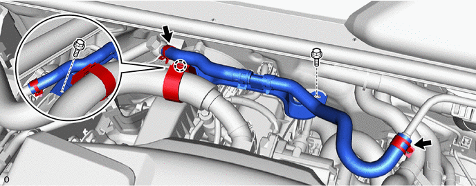
REMOVE VACUUM HOSE ASSEMBLY (for GD Series Engine, LHD)
-
Using pliers, grip the claws of the clip and slide the clip to disconnect the vacuum hose.
Note
Do not apply excessive force to the vacuum hose.
-
Detach the claw.
-
Remove the 2 bolts and remove the vacuum hose assembly.
-
-
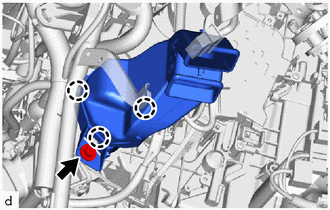
REMOVE NO. 2 WIRING HARNESS PROTECTOR (for GD Series Engine, RHD)
-
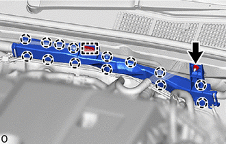
Remove the nut.
-
Detach the claw, guide and remove the No. 2 wiring harness protector.
-
-
REMOVE VACUUM HOSE ASSEMBLY (for GD Series Engine, RHD)
-
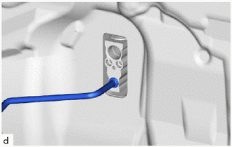
Using pliers, grip the claws of the clip and slide the clip to disconnect the vacuum hose.
Note
Do not apply excessive force to the vacuum hose.
-
Detach the claw.
-
Remove the 2 bolts and remove the vacuum hose assembly.
-
-
DISCONNECT AIR CONDITIONER TUBE AND ACCESSORY ASSEMBLY (for 1GD-FTV, 2GD-FTV)
-
Remove the bolt and disconnect the air conditioner tube and accessory assembly.
-
Remove the 2 O-rings from the air conditioner tube and accessory assembly.
Note
Seal the openings of the disconnected parts using vinyl tape to prevent the entry of moisture and foreign matter.
-
-
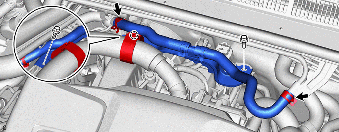
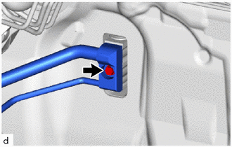
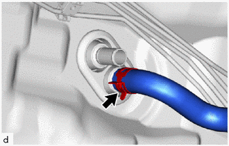
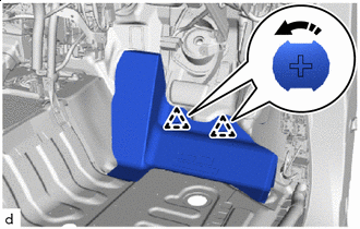
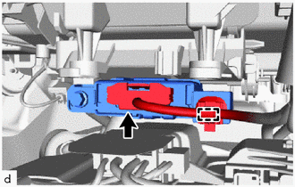
DISCONNECT SUCTION PIPE SUB-ASSEMBLY (except 1GD-FTV, 2GD-FTV)
-
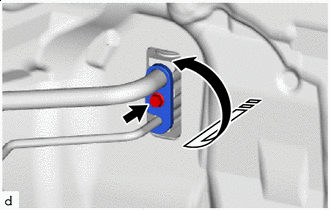

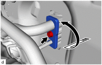
Remove in this Direction Remove the bolt and rotate the hook connector as shown in the illustration.
-
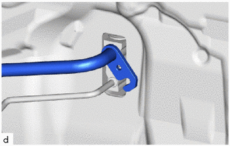
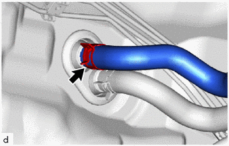
Disconnect the suction pipe sub-assembly.
-
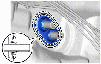
Remove the O-ring from the suction pipe sub-assembly.
Note
Seal the openings of the disconnected parts using vinyl tape to prevent the entry of moisture and foreign matter.
-
-
DISCONNECT AIR CONDITIONER TUBE AND ACCESSORY ASSEMBLY (except 1GD-FTV, 2GD-FTV)
-
Disconnect the air conditioner tube and accessory assembly.
-
Remove the O-ring from the air conditioner tube and accessory assembly.
Note
Seal the openings of the disconnected parts using vinyl tape to prevent the entry of moisture and foreign matter.
-
-
DISCONNECT AIR CONDITIONER TUBE AND ACCESSORY ASSEMBLY (except 1GD-FTV, 2GD-FTV, w/ Sub-cool Accelerator)
-
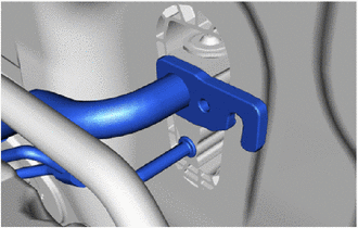
Remove in this Direction Remove the bolt and rotate the hook connector as shown in the illustration.
-
Disconnect the air conditioner tube and accessory assembly.
-
Remove the 2 O-rings from the air conditioner tube and accessory assembly.
Note
Seal the openings of the disconnected parts using vinyl tape to prevent the entry of moisture and foreign matter.
-
-
DISCONNECT HEATER WATER OUTLET HOSE
-
Using pliers, grip the claws of the clip and slide the clip to disconnect the heater water outlet hose.
Note
-
Do not apply excessive force to the heater water outlet hose.
-
Prepare a drain pan or cloth in case the coolant leaks.
-
-
-
DISCONNECT HEATER WATER INLET HOSE
-
Using pliers, grip the claws of the clip and slide the clip to disconnect the heater water inlet hose.
Note
-
Do not apply excessive force to the heater water inlet hose.
-
Prepare a drain pan or cloth in case the coolant leaks.
-
-
-
REMOVE HEATER GROMMET
-
Detach the claw and remove the heater grommet.
-
-
REMOVE FRONT SEAT ASSEMBLY RH
-
for Manual Seat:
-
for Power Seat:
-
-
REMOVE FRONT SEAT ASSEMBLY LH
Tech Tips
Use the same procedure described for the RH side.
-
REMOVE LOWER INSTRUMENT PANEL SUB-ASSEMBLY
-
REMOVE TELEMATICS TRANSCEIVER (w/ Telematics Transceiver)
-
REMOVE NO. 2 AIR DUCT
-
Remove the bolt.
-
Detach the claw and remove the No. 2 air duct.
Note
-
When removing, do not crack or deform the lower heater case of the air conditioning radiator assembly.
-
If the No. 2 air duct is reused, it may fall off or abnormal noise may occur. Therefore, make sure to replace it with a new one.
-
-
-
REMOVE NO. 1 AIR DUCT
-
Detach the claw and remove the No. 1 air duct.
Note
-
When removing, do not crack or deform the lower heater case of the air conditioning radiator assembly.
-
If the No. 1 air duct is reused, it may fall off or abnormal noise may occur. Therefore, make sure to replace it with a new one.
-
-
-
REMOVE STEERING COLUMN ASSEMBLY
-
REMOVE FRONT DOOR SCUFF PLATE LH
-
REMOVE COWL SIDE TRIM BOARD LH
-
REMOVE FRONT DOOR SCUFF PLATE RH
-
REMOVE COWL SIDE TRIM BOARD RH
-
REMOVE REAR DOOR SCUFF PLATE LH
-
REMOVE REAR DOOR SCUFF PLATE RH
-
REMOVE LOWER CENTER PILLAR GARNISH LH
-
REMOVE LOWER CENTER PILLAR GARNISH RH
-
REMOVE FRONT FLOOR CARPET ASSEMBLY
-
for RHD:
Remove the 5 clips.
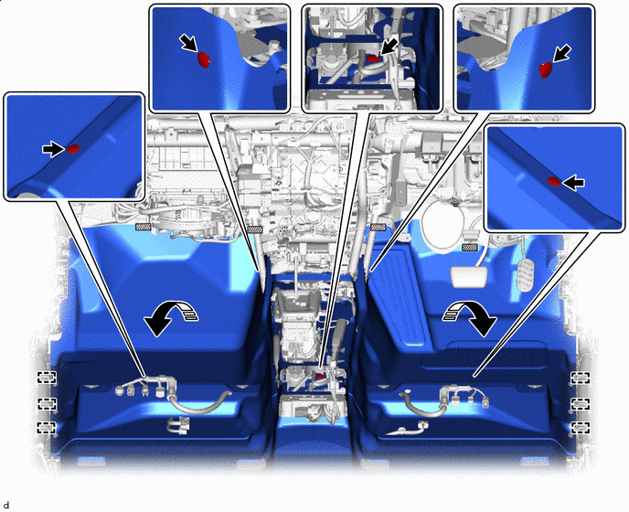

Fastener Remove in this Direction -
for LHD:
Remove the 6 clips.
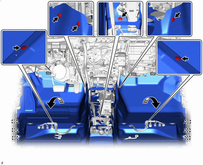
Fastener Remove in this Direction -
Detach each fastener.
-
Detach the guide and fold back the front floor carpet assembly as shown in the illustration.
-
-
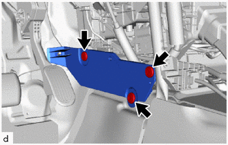
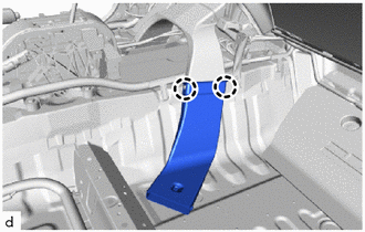
REMOVE NO. 1 INSTRUMENT PANEL INNER BRACKET COVER LH (for LHD)
-
Remove the 3 clips and No. 1 instrument panel inner bracket cover LH
-
-
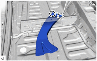
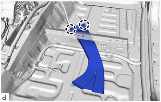
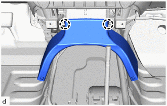
REMOVE NO. 3 DASH PANEL INSULATOR PAD
-
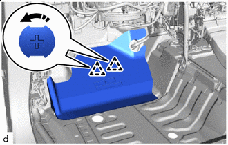
Remove in this Direction Remove the No. 3 dash panel insulator pad as shown in the illustration.
-
-
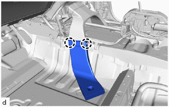
REMOVE NO. 2 DASH PANEL INSULATOR PAD
-
Remove in this Direction Remove the No. 2 dash panel insulator pad as shown in the illustration.
-
-
REMOVE NO. 4 REAR AIR DUCT (w/ Rear Foot Duct)
-
Detach the claw and remove the No. 4 rear air duct.
-
-
REMOVE NO. 5 REAR AIR DUCT (w/ Rear Foot Duct)
-
Detach the claw and remove the No. 5 rear air duct.
-
-
REMOVE NO. 2 REAR AIR DUCT (w/ Rear Foot Duct)
-
Detach the claw and remove the No. 2 rear air duct.
-
-
REMOVE NO. 3 REAR AIR DUCT (w/ Rear Foot Duct)
-
Detach the claw and remove the No. 3 rear air duct.
-
-
REMOVE NO. 1 REAR AIR DUCT (w/ Rear Foot Duct)
-
Remove the 2 clips and remove the No. 1 rear air duct.
-
-
REMOVE NO. 1 INSTRUMENT PANEL BRACE SUB-ASSEMBLY
-

Nut 
Bolt 
Screw Detach the clamp.
-
Remove the nut, bolt, 4 screws and No. 1 instrument panel brace sub-assembly.
-
-
REMOVE NO. 2 INSTRUMENT PANEL BRACE SUB-ASSEMBLY
-

Nut Bolt Screw Remove the nut, bolt, 3 screws and No. 2 instrument panel brace sub-assembly.
-
-
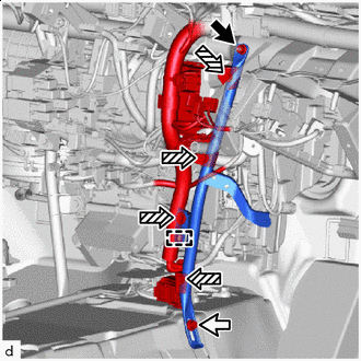
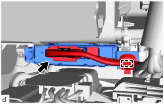
DISCONNECT INSTRUMENT PANEL WIRE
-
for Automatic Air Conditioning System:
-
Disconnect the connector.
-
Detach the clamp.
-
-
for Manual Air Conditioning System:
-
Disconnect the connector.
-
Detach the clamp.
-
-
Remove each bolt and each ground wire.
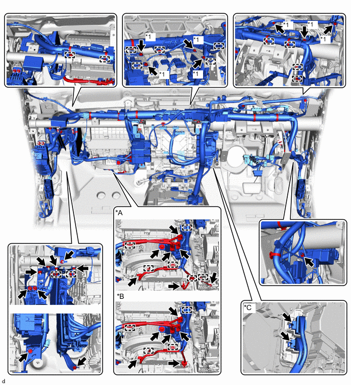
*A for Manual Air Conditioning System *B for Automatic Air Conditioning System *C w/ PTC Heater - - *1 Ground Wire - - -
Disconnect each connector and detach each clamp.
-
Remove each bolt, nut and screw, and then disconnect the instrument panel wire.
-
-
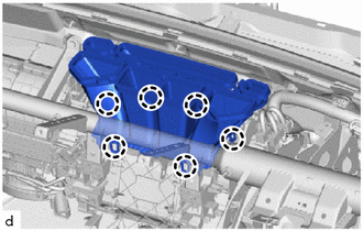
REMOVE INSTRUMENT PANEL REINFORCEMENT ASSEMBLY
Note
-
Be sure to support the air conditioning unit assembly when removing it because failure to do so may cause the bracket of the air conditioning unit assembly to break.
-
When removing the air conditioning unit assembly, eliminate static electricity by touching the vehicle body to prevent the components from being damaged.
-
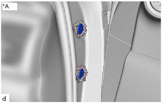
*A for Driver Side Protective Tape Put protective tape around the hole plug.
-
Using a screwdriver with its tip wrapped with protective tape, remove the 2 hole plugs.
-
for Automatic Transmission:
Remove the 11 bolts.
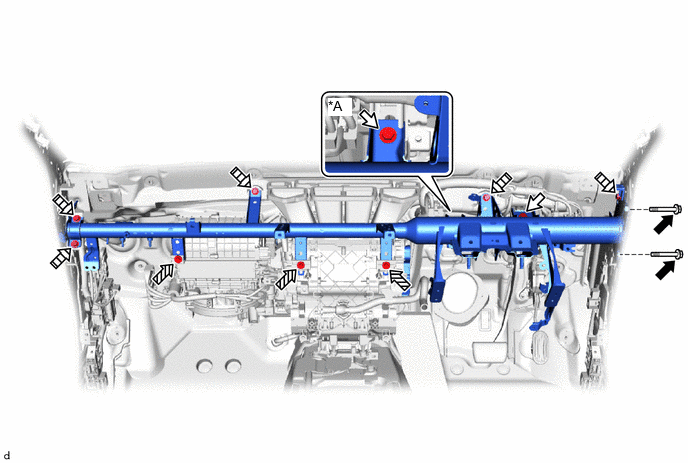
*A for Manual Transmission - - Bolt A Bolt B Bolt C 
Bolt D -
for Manual Transmission:
Remove the 12 bolts.
-
-
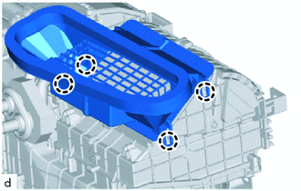
REMOVE LOWER DEFROSTER NOZZLE ASSEMBLY
-
Detach the claw and remove the lower defroster nozzle assembly.
-
-
REMOVE AIR CONDITIONING UNIT ASSEMBLY
Note
-
Be sure to support the air conditioning unit assembly when removing it because failure to do so may cause the bracket of the air conditioning unit assembly to break.
-
When disassembling the air conditioning unit assembly, eliminate static electricity by touching the vehicle body to prevent the components from being damaged.
-
Disconnect the drain cooler hose.
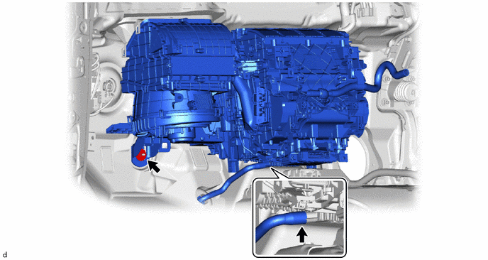
-
Remove the nut and air conditioning unit assembly and instrument panel reinforcement assembly.
-
-
REMOVE NO. 3 AIR DUCT
-
Detach the claw and remove the No. 3 air duct.
-