FRONT AIR CONDITIONING UNIT REMOVAL
CAUTION / NOTICE / HINT
Tech Tips
-
Use the same procedure for RHD and LHD vehicles.
-
The procedure listed below is for RHD vehicles.
The necessary procedures (adjustment, calibration, initialization or registration) that must be performed after parts are removed, installed or replaced during the front air conditioning unit removal/installation are shown below.
| Replacement Part or Procedure | Necessary Procedures | Effects / Inoperative when not Performed | Link |
|---|---|---|---|
| Disconnect cable from negative battery terminal |
w/ Power Back Door System: |
Power back door system |
CAUTION:
Some of these service operations affect the SRS airbag system. Read the precautionary notices concerning the SRS airbag system before servicing.
PROCEDURE
-
RECOVER REFRIGERANT FROM REFRIGERATION SYSTEM
-
DRAIN ENGINE COOLANT (for Automatic Air Conditioning System, Manual Air Conditioning System)
-
for 1GR-FE:
-
for 1KD-FTV:
-
for 2KD-FTV:
-
for 1GD-FTV:
-
for 2GD-FTV:
-
for 2TR-FE:
-
for 5L-E:
-
-
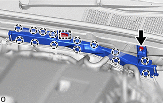
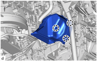
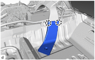
REMOVE NO. 2 WIRING HARNESS PROTECTOR (for GD Series Engine, LHD)
-
Remove the 2 nuts.
-
Detach the claw and remove the No. 2 wiring harness protector.
-
-
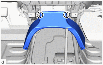
REMOVE VACUUM HOSE ASSEMBLY (for GD Series Engine, LHD)
-
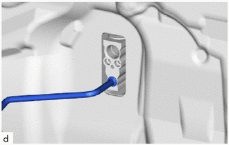
Using pliers, grip the claws of the clip and slide the clip to disconnect the vacuum hose.
Note
Do not apply excessive force to the vacuum hose.
-
Detach the claw.
-
Remove the 2 bolts and remove the vacuum hose assembly.
-
-
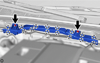
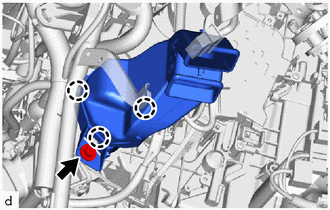
REMOVE NO. 2 WIRING HARNESS PROTECTOR (for GD Series Engine, RHD)
-
Remove the 2 nuts.
-
Detach the claw, guide and remove the No. 2 wiring harness protector.
-
-
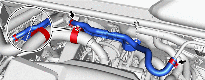
REMOVE VACUUM HOSE ASSEMBLY (for GD Series Engine, RHD)
-
Using pliers, grip the claws of the clip and slide the clip to disconnect the vacuum hose.
Note
Do not apply excessive force to the vacuum hose.
-
Detach the claw.
-
Remove the 2 bolts and remove the vacuum hose assembly.
-
-
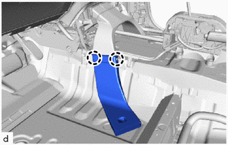
DISCONNECT AIR CONDITIONER TUBE AND ACCESSORY ASSEMBLY (for 1GD-FTV, 2GD-FTV)
-
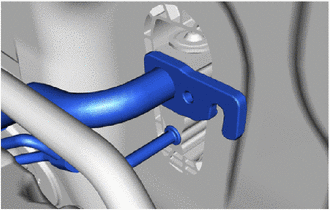
Remove the bolt and disconnect the air conditioner tube and accessory assembly.
-
Remove the 2 O-rings from the air conditioner tube and accessory assembly.
Note
Seal the openings of the disconnected parts using vinyl tape to prevent the entry of moisture and foreign matter.
-
-
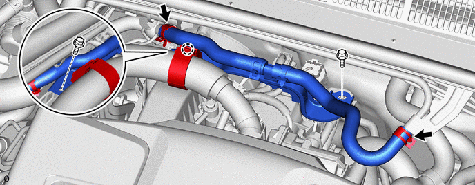
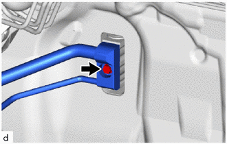
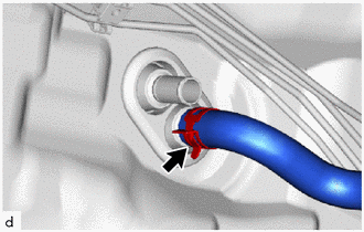
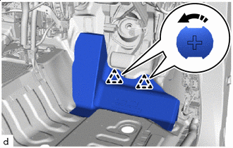
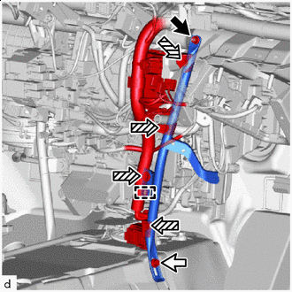
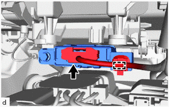
DISCONNECT SUCTION PIPE SUB-ASSEMBLY (except 1GD-FTV, 2GD-FTV)
-
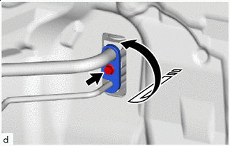

Remove in this Direction Remove the bolt and rotate the hook connector as shown in the illustration.
-
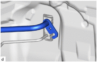
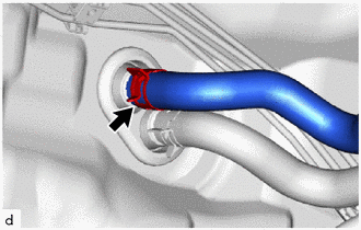
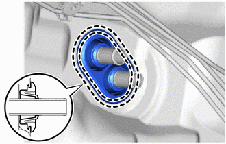
Disconnect the suction pipe sub-assembly.
-
Remove the O-ring from the suction pipe sub-assembly.
Note
Seal the openings of the disconnected parts using vinyl tape to prevent the entry of moisture and foreign matter.
-
-
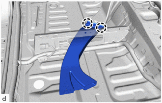
DISCONNECT AIR CONDITIONER TUBE AND ACCESSORY ASSEMBLY (except 1GD-FTV, 2GD-FTV)
-
Disconnect the air conditioner tube and accessory assembly.
-
Remove the O-ring from the air conditioner tube and accessory assembly.
Note
Seal the openings of the disconnected parts using vinyl tape to prevent the entry of moisture and foreign matter.
-
-
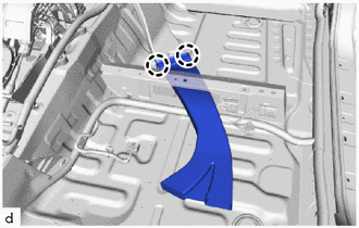
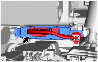
DISCONNECT AIR CONDITIONER TUBE AND ACCESSORY ASSEMBLY (except 1GD-FTV, 2GD-FTV, w/ Sub-cool Accelerator)
-
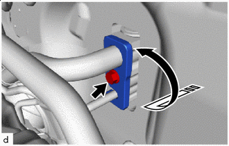
Remove in this Direction Remove the bolt and rotate the hook connector as shown in the illustration.
-
Disconnect the air conditioner tube and accessory assembly.
-
Remove the 2 O-rings from the air conditioner tube and accessory assembly.
Note
Seal the openings of the disconnected parts using vinyl tape to prevent the entry of moisture and foreign matter.
-
-
DISCONNECT HEATER WATER OUTLET HOSE (for Automatic Air Conditioning System, Manual Air Conditioning System)
-
Using pliers, grip the claws of the clip and slide the clip to disconnect the heater water outlet hose.
Note
-
Do not apply excessive force to the heater water outlet hose.
-
Prepare a drain pan or cloth in case the coolant leaks.
-
-
-
DISCONNECT HEATER WATER INLET HOSE (for Automatic Air Conditioning System, Manual Air Conditioning System)
-
Using pliers, grip the claws of the clip and slide the clip to disconnect the heater water inlet hose.
Note
-
Do not apply excessive force to the heater water inlet hose.
-
Prepare a drain pan or cloth in case the coolant leaks.
-
-
-
REMOVE HEATER GROMMET (for Automatic Air Conditioning System, Manual Air Conditioning System)
-
Detach the claw and remove the heater grommet.
-
-
REMOVE FRONT SEAT ASSEMBLY LH
-
for Manual Seat:
-
for Power Seat:
-
-
REMOVE FRONT SEAT ASSEMBLY RH
Tech Tips
Use the same procedure described for the LH side.
-
REMOVE LOWER INSTRUMENT PANEL SUB-ASSEMBLY
-
REMOVE NO. 2 AIR DUCT
-
Remove the bolt.
-
Detach the claw and remove the No. 2 air duct.
Note
-
When removing, do not crack or deform the lower heater case of the air conditioning radiator assembly.
-
If the No. 2 air duct is reused, it may fall off or abnormal noise may occur. Therefore, make sure to replace it with a new one.
-
-
-
REMOVE NO. 1 AIR DUCT
-
Detach the claw and remove the No. 1 air duct.
Note
-
When removing, do not crack or deform the lower heater case of the air conditioning radiator assembly.
-
If the No. 1 air duct is reused, it may fall off or abnormal noise may occur. Therefore, make sure to replace it with a new one.
-
-
-
REMOVE STEERING COLUMN ASSEMBLY
-
REMOVE FRONT DOOR SCUFF PLATE LH
-
REMOVE COWL SIDE TRIM BOARD LH
-
REMOVE FRONT DOOR SCUFF PLATE RH
-
REMOVE COWL SIDE TRIM BOARD RH
-
REMOVE REAR DOOR SCUFF PLATE LH
-
REMOVE REAR DOOR SCUFF PLATE RH
-
REMOVE LOWER CENTER PILLAR GARNISH LH
-
REMOVE LOWER CENTER PILLAR GARNISH RH
-
REMOVE FRONT FLOOR CARPET ASSEMBLY
-
for RHD:
Remove the 5 clips.
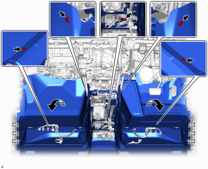

Fastener Remove in this Direction -
for LHD:
Remove the 6 clips.
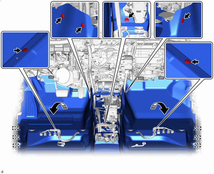
Fastener Remove in this Direction -
Detach each fastener.
-
Detach the guide and fold back the front floor carpet assembly as shown in the illustration.
-
-
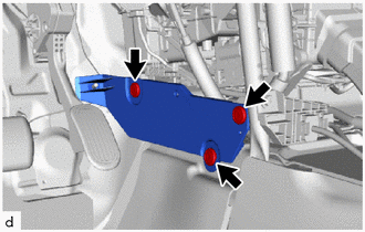
REMOVE NO. 1 INSTRUMENT PANEL INNER BRACKET COVER LH (for LHD)
-
Remove the 3 clips and No. 1 instrument panel inner bracket cover LH
-
-
REMOVE NO. 3 DASH PANEL INSULATOR PAD
-
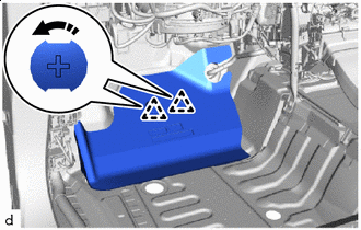
Remove in this Direction Remove the No. 3 dash panel insulator pad as shown in the illustration.
-
-
REMOVE NO. 2 DASH PANEL INSULATOR PAD
-
Remove in this Direction Remove the No. 2 dash panel insulator pad as shown in the illustration.
-
-
REMOVE NO. 4 REAR AIR DUCT (w/ Rear Foot Duct)
-
Detach the claw and remove the No. 4 rear air duct.
-
-
REMOVE NO. 5 REAR AIR DUCT (w/ Rear Foot Duct)
-
Detach the claw and remove the No. 5 rear air duct.
-
-
REMOVE NO. 2 REAR AIR DUCT (w/ Rear Foot Duct)
-
Detach the claw and remove the No. 2 rear air duct.
-
-
REMOVE NO. 3 REAR AIR DUCT (w/ Rear Foot Duct)
-
Detach the claw and remove the No. 3 rear air duct.
-
-
REMOVE NO. 1 REAR AIR DUCT (w/ Rear Foot Duct)
-
Remove the 2 clips and remove the No. 1 rear air duct.
-
-
REMOVE NO. 1 INSTRUMENT PANEL BRACE SUB-ASSEMBLY
-

Nut 
Bolt 
Screw Detach the clamp.
-
Remove the nut, bolt, 4 screws and No. 1 instrument panel brace sub-assembly.
-
-
REMOVE NO. 2 INSTRUMENT PANEL BRACE SUB-ASSEMBLY
-

Nut Bolt Screw Remove the nut, bolt, 3 screws and No. 2 instrument panel brace sub-assembly.
-
-
DISCONNECT INSTRUMENT PANEL WIRE
-
for Automatic Air Conditioning System:
-
Disconnect the connector.
-
Detach the clamp.
-
-
for Manual Air Conditioning System:
-
Disconnect the connector.
-
Detach the clamp.
-
-
Remove each bolt and each ground wire.
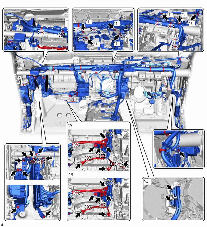
*A for Manual Air Conditioning System *B for Automatic Air Conditioning System *C w/ PTC Heater - - *1 Ground Wire - - -
Disconnect each connector and detach each clamp.
-
Remove each bolt, nut and screw, and then disconnect the instrument panel wire.
-
-
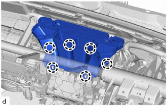
REMOVE INSTRUMENT PANEL REINFORCEMENT ASSEMBLY
Note
-
Be sure to support the air conditioning unit assembly when removing it because failure to do so may cause the bracket of the air conditioning unit assembly to break.
-
When removing the air conditioning unit assembly, eliminate static electricity by touching the vehicle body to prevent the components from being damaged.
-
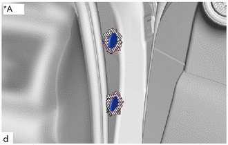
*A for Driver Side Protective Tape Put protective tape around the hole plug.
-
Using a screwdriver with its tip wrapped with protective tape, remove the 2 hole plugs.
-
for Automatic Transmission:
Remove the 11 bolts.
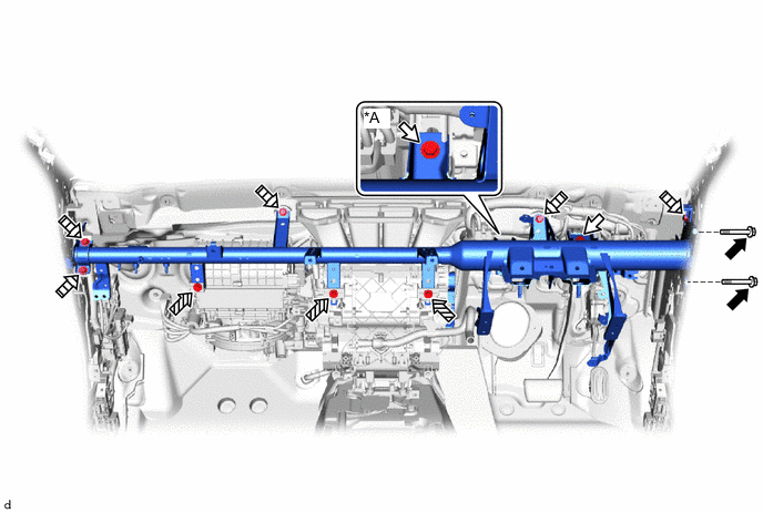
*A for Manual Transmission - - Bolt A Bolt B Bolt C 
Bolt D -
for Manual Transmission:
Remove the 12 bolts.
-
-
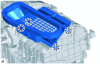
REMOVE DEFROSTER NOZZLE ASSEMBLY
-
Detach the claw and remove the defroster nozzle assembly.
-
-
REMOVE AIR CONDITIONING UNIT ASSEMBLY
Note
-
Be sure to support the air conditioning unit assembly when removing it because failure to do so may cause the bracket of the air conditioning unit assembly to break.
-
When disassembling the air conditioning unit assembly, eliminate static electricity by touching the vehicle body to prevent the components from being damaged.
-
Disconnect the drain cooler hose.
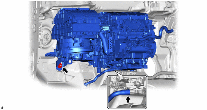
-
Remove the nut and air conditioning unit assembly and instrument panel reinforcement assembly.
-
-
REMOVE NO. 3 AIR DUCT
-
Detach the claw and remove the No. 3 air duct.
-