REAR AIR CONDITIONING UNIT INSTALLATION
PROCEDURE
-
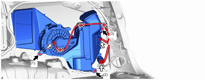
INSTALL REAR COOLING UNIT ASSEMBLY (for Automatic Air Conditioning System)
-
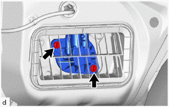
Install the rear cooling unit assembly with the 3 bolts and tighten the bolts in the order shown in the illustration.

Bolt 
Connector - Torque:
- 9.8 N*m { 100 kgf*cm, 87 in.*lbf }
-
Attach the clamp.
-
Connect the 2 connectors.
-
Install the 2 bolts.
- Torque:
- 9.8 N*m { 100 kgf*cm, 87 in.*lbf }
-
-
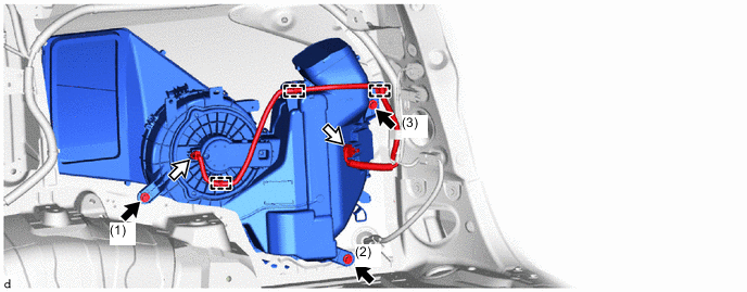
INSTALL REAR COOLING UNIT ASSEMBLY (for Manual Air Conditioning System, Manual Cooler System)
-
Install the rear cooling unit assembly with the 3 bolts and tighten the bolts in the order shown in the illustration.
Bolt Connector - Torque:
- 9.8 N*m { 100 kgf*cm, 87 in.*lbf }
-
Attach the clamp.
-
Connect the 3 connectors.
-
Install the 2 bolts.
- Torque:
- 9.8 N*m { 100 kgf*cm, 87 in.*lbf }
-
-
CONNECT COOLER REFRIGERANT LIQUID PIPE C
-
Remove the vinyl tape from the cooler refrigerant liquid pipe C.
-
Sufficiently apply compressor oil to a new O-ring and the fitting surface of the cooler refrigerant liquid pipe C.
Compressor Oil ND-OIL 8 or equivalent -
Install the O-ring to the cooler refrigerant liquid pipe C.
Note
Keep the O-ring and O-ring fitting surfaces free of foreign matter.
-
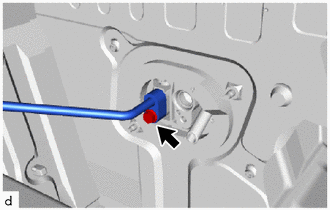
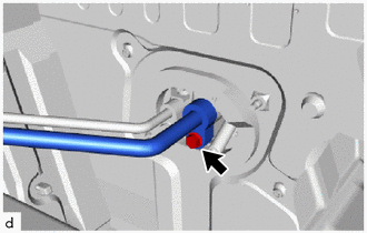
Connect the cooler refrigerant liquid pipe C.
-
Install the bolt.
- Torque:
- 5.4 N*m { 55 kgf*cm, 48 in.*lbf }
-
-
CONNECT COOLER REFRIGERANT SUCTION PIPE A
-
Remove the vinyl tape from the cooler refrigerant suction pipe A.
-
Sufficiently apply compressor oil to a new O-ring and the fitting surface of the cooler refrigerant suction pipe A.
Compressor Oil ND-OIL 8 or equivalent -
Install the O-ring to the cooler refrigerant suction pipe A.
Note
Keep the O-ring and O-ring fitting surfaces free of foreign matter.
-
Connect the cooler refrigerant suction pipe A.
-
Install the bolt.
- Torque:
- 5.4 N*m { 55 kgf*cm, 48 in.*lbf }
-
-
INSTALL REAR BUMPER COVER
-
INSTALL NO. 5 AIR DUCT SUB-ASSEMBLY
-
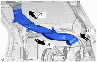

Order of Installation Install the No. 5 air duct sub-assembly as shown in the illustration.
-
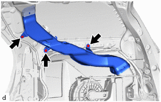
Install the 3 clips.
-
-
INSTALL REAR UPPER PILLAR GARNISH RH
-
INSTALL SEAT BELT ANCHOR COVER CAP
-
INSTALL QUARTER PILLAR GARNISH RH
-
INSTALL SEAT BELT ANCHOR COVER CAP
-
INSTALL QUARTER INSIDE TRIM BOARD RH
-
INSTALL REAR NO. 2 SEAT LAP BELT OUTER ANCHOR COVER (w/ Rear No. 2 Seat)
-
INSTALL REAR NO. 1 SEAT LAP BELT OUTER ANCHOR COVER
-
INSTALL BACK DOOR SCUFF PLATE
-
INSTALL REAR DOOR SCUFF PLATE RH
-
INSTALL REAR NO. 2 SEAT ASSEMBLY (w/ Rear No. 2 Seat)
-
CHARGE AIR CONDITIONING SYSTEM WITH REFRIGERANT
-
WARM UP ENGINE
-
INSPECT FOR REFRIGERANT LEAK