AIR CONDITIONING SYSTEM(for Automatic Air Conditioning System) Viscous Heater with Magnet Clutch Circuit
DESCRIPTION
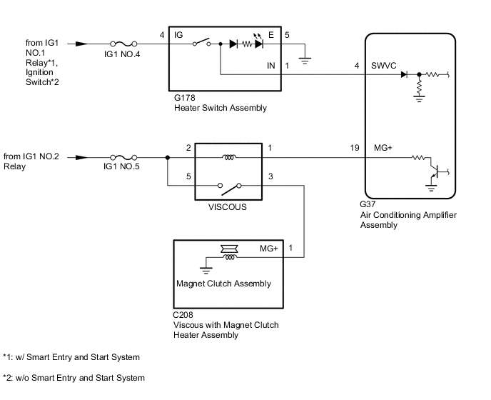
When the heater switch assembly is pushed, the air conditioning amplifier assembly turns on the viscous heater relay and operates the viscous heater. If the viscous heater does not operate when the heater switch assembly is pushed, there may be a problem in the circuit shown below.
WIRING DIAGRAM
CAUTION / NOTICE / HINT
Note
When the servo motor or air conditioning amplifier assembly is replaced, be sure to perform servo motor initialization.
Tech Tips
Inspect the fuses for circuits related to this system before performing the following procedure.
PROCEDURE
-
READ VALUE USING GTS (IDLE UP/PWR HEAT SWITCH)
-
Connect the GTS to the DLC3.
-
Turn the ignition switch to ON.
-
Turn the GTS on.
-
Enter the following menus: Body Electrical / Air Conditioner / Data List.
-
Check the value(s) by referring to the table below.
Body Electrical > Air Conditioner > Data ListTester Display Measurement Item Range Normal Condition Diagnostic Note IDLE UP/PWR HEAT Switch Heater switch assembly ON or OFF ON: Heater switch assembly on
OFF: Heater switch assembly off
-
Body Electrical > Air Conditioner > Data ListTester Display IDLE UP/PWR HEAT Switch OK The display is as specified in the normal condition column. Result Proceed to OK NG
NG 
CHECK HARNESS AND CONNECTOR (HEATER SWITCH ASSEMBLY - BATTERY AND BODY GROUND) Click here
OK 
-
-
PERFORM ACTIVE TEST USING GTS
-
Connect the GTS to the DLC3.
-
Turn the ignition switch to ON.
-
Turn the GTS on.
-
Enter the following menus: Body Electrical / Air Conditioner / Active Test.
-
Check the operation by referring to the table below.
Body Electrical > Air Conditioner > Active TestTester Display Measurement Item Control Range Diagnostic Note Viscous Heater Viscous heater relay ON/OFF -
Body Electrical > Air Conditioner > Active TestTester Display Viscous Heater OK Viscous heater relay operates. Result Proceed to OK NG
OK 
REPLACE AIR CONDITIONING AMPLIFIER ASSEMBLY Click here
NG
INSPECT VISCOUS HEATER RELAY (VISCOUS) Click here
-
-
CHECK HARNESS AND CONNECTOR (HEATER SWITCH ASSEMBLY - BATTERY AND BODY GROUND)
-
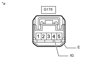
*a Front view of wire harness connector
(to Heater Switch Assembly)
Disconnect the heater switch assembly connector.
-
Measure the resistance according to the value(s) in the table below.
Standard Resistance Tester Connection Condition Specified Condition G178-5 (E) - Body ground Always Below 1 Ω -
Measure the voltage according to the value(s) in the table below.
Standard Voltage Tester Connection Switch Condition Specified Condition G178-4 (IG) - Body ground Ignition switch off Below 1 V Ignition switch ON 11 to 14 V Result Proceed to OK NG
NG
REPAIR OR REPLACE HARNESS OR CONNECTOR
OK
-
-
INSPECT HEATER SWITCH ASSEMBLY
-
Remove the heater switch assembly.
-
Inspect the heater switch assembly.
Result Proceed to OK NG
NG
REPLACE HEATER SWITCH ASSEMBLY Click here
OK
-
-
CHECK HARNESS AND CONNECTOR (HEATER SWITCH ASSEMBLY - AIR CONDITIONING AMPLIFIER ASSEMBLY)
-
Disconnect the G178 heater switch assembly connector
-
Disconnect the G37 air conditioning amplifier assembly connector.
-
Measure the resistance according to the value(s) in the table below.
Standard Resistance Tester Connection Condition Specified Condition G178-1 (IN) - G37-4 (SWVC) Always Below 1 Ω G178-1 (IN) or G37-4 (SWVC) - Body ground Always 10 kΩ or higher Result Proceed to OK NG
OK
REPLACE AIR CONDITIONING AMPLIFIER ASSEMBLY Click here
NG
REPAIR OR REPLACE HARNESS OR CONNECTOR
-
-
INSPECT VISCOUS HEATER RELAY (VISCOUS)
-
Remove the viscous heater relay (VISCOUS) from the No. 5 instrument panel relay block.
-
Inspect the viscous heater relay (VISCOUS).
Result Proceed to OK NG
NG
REPLACE VISCOUS HEATER RELAY
OK
-
-
CHECK HARNESS AND CONNECTOR (AIR CONDITIONING AMPLIFIER - BATTERY)
-
Disconnect the air conditioning amplifier assembly connector.
-
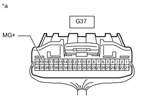
*a Rear view of wire harness connector
(to Air Conditioning Amplifier Assembly)
Measure the voltage according to the value(s) in the table below.
Standard Voltage Tester Connection Switch Condition Specified Condition G37-19 (MG+) - Body ground Ignition switch off Below 1 V G37-19 (MG+) - Body ground Ignition switch ON 11 to 14 V Result Proceed to OK NG
NG
REPAIR OR REPLACE HARNESS OR CONNECTOR
OK
-
-
INSPECT VISCOUS WITH MAGNET CLUTCH HEATER ASSEMBLY
-
Remove the viscous with magnet clutch heater assembly.
-
Inspect the viscous with magnet clutch heater assembly.
Result Proceed to OK NG
NG
REPLACE VISCOUS WITH MAGNET CLUTCH HEATER ASSEMBLY Click here
OK
-
-
CHECK HARNESS AND CONNECTOR (VISCOUS RELAY - VISCOUS WITH MAGNET CLUTCH HEATER ASSEMBLY AND BATTERY)
-
Remove the viscous heater relay (VISCOUS) from the No. 5 instrument panel relay block.
-
Disconnect the C208 viscous with magnet clutch heater assembly connector.
-
Measure the resistance according to the value(s) in the table below.
Standard Resistance Tester Connection Condition Specified Condition Relay terminal 3 - C208-1 (MG+) Always Below 1 Ω Relay terminal 3 or C208-1 (MG+) - Body ground Always 10 kΩ or higher -
Measure the voltage according to the value(s) in the table below.
Standard Voltage Tester Connection Switch Condition Specified Condition Relay terminal 2 - Body ground Ignition switch off Below 1 V Relay terminal 2 - Body ground Ignition switch ON 11 to 14 V Result Proceed to OK NG
OK
REPLACE AIR CONDITIONING AMPLIFIER ASSEMBLY Click here
NG
REPAIR OR REPLACE HARNESS OR CONNECTOR
-