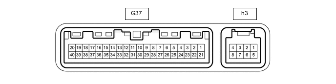
AIR CONDITIONING SYSTEM(for Automatic Air Conditioning System) TERMINALS OF ECU
-
AIR CONDITIONING AMPLIFIER ASSEMBLY (for Front)
-
Disconnect the G37 air conditioning amplifier assembly connector.
-
Measure the resistance and voltage according to the value(s) in the table below.
Terminal No.
(Symbol)
Wiring Color Terminal Description Condition Specified Condition G37-1 (IG+) - Body ground G - Body ground Power source (IG) Ignition switch ON 11 to 14 V Ignition switch off Below 1 V G37-14 (GND) - Body ground W-B - Body ground Ground for main power supply Always Below 1 Ω G37-21 (B) - Body ground W - Body ground Power source (Back-up) Always 11 to 14 V -
Reconnect the G37 air conditioning amplifier assembly connector.
-
Disconnect the h3 air conditioning harness assembly connector.
-
Measure the resistance, voltage and check for waveform according to the value(s) in the table below.
Terminal No.
(Symbol)
Wiring Color Terminal Description Condition Specified Condition G37-3 (PTC3) - Body ground*1 SB - Body ground Quick heater assembly operation signal
-
Engine starts
-
ECO mode switch: Off
-
Temperature settings: MAX HOT
-
Ambient temperature: 10°C (50°F) or lower
-
Engine coolant temperature: 64°C (147°F) or lower
-
Light control switch: Off
-
Blower switch: Off → on (after 30 seconds)
11 to 14 V → Below 1 V G37-4 (SWVC) - Body ground*2, *3 R - Body ground Idle up switch operation signal
-
Engine running
-
"A/C" switch: On
-
Blower switch: On (LO level)
-
Idle up switch: Off → on
Below 1 V → 11 to 14 V G37-9 (PSW) - Body ground L - Body ground Air conditioner pressure switch signal
-
Engine running
-
Refrigerant pressure normal
Below 1 V
-
Engine running
-
Refrigerant pressure less than 0.196 MPa (2.0 kgf/cm2, 28 psi) or more than 3.14 MPa (32.0 kgf/cm2, 455 psi)
11 to 14 V G37-11 (TX+) GR CAN communication line - - G37-12 (TX-) W CAN communication line - - G37-17 (AC1) - Body ground GR - Body ground Idle-up request signal
-
Engine running
-
Blower switch: On (LO level)
-
"A/C" switch: Off
11 to 14 V
-
Engine running
-
Blower switch: On (LO level)
-
"A/C" switch: On
Below 1 V G37-19 (MG+) - Body ground*2 P - Body ground Viscous with magnetic clutch heater assembly operation signal
-
Engine running
-
Blower switch: On (LO level)
-
Heater switch assembly: Off or on (magnet clutch off)
11 to 14 V
-
Engine running
-
Blower switch: On (LO level)
-
Heater switch assembly: On (magnet clutch on)
Below 1 V G37-20 (MGC) - Body ground V - Body ground Magnet clutch drive output signal
-
Engine running
-
Blower switch: On (LO level)
-
"A/C" switch: Off or on (magnet clutch off)
11 to 14 V
-
Engine running
-
Blower switch: On (LO level)
-
"A/C" switch: On (magnet clutch on)
Below 1 V G37-22 (BLW) - Body ground P - Body ground Blower motor speed control signal
-
Ignition switch ON
-
Blower switch: LO
Pulse generation
(See Waveform 1)
G37-23 (RCRL) - Body ground Y - Body ground Rear blower motor speed control signal
-
Ignition switch ON
-
Blower switch: LO
Pulse generation
(See Waveform 1)
G37-24 (ACT) - Body ground LG - Body ground Magnet clutch on permit input signal
-
Engine running
-
Blower switch: On (LO level)
-
"A/C" switch: Off or on (magnet clutch off)
Below 1 V
-
Engine running
-
Blower switch: On (LO level)
-
"A/C" switch: On (magnet clutch on)
4.5 to 5.5 V G37-29 (TR) - G37-34 (SG-2) V - L Room temperature sensor signal
-
Ignition switch ON
-
Cabin temperature: 25°C (77°F)
1.8 to 2.2 V
-
Ignition switch ON
-
Cabin temperature: 40°C (104°F)
1.2 to 1.6 V G37-30 (S5-3) - Body ground G - Body ground Power supply for solar sensor Ignition switch ON 4.5 to 5.5 V G37-33 (TSD) - Body ground P - Body ground Solar sensor signal
-
Ignition switch ON
-
Solar sensor subjected to electric light
-
Vehicle indoors
0.8 to 4.3 V
-
Ignition switch ON
-
Solar sensor covered with cloth
-
Vehicle indoors
Below 0.8 V G37-34 (SG-2) - Body ground L - Body ground Ground for room temperature sensor Always Below 1 Ω G37-37 (LIN1) - Body ground R - Body ground LIN communication signal Ignition switch ON Pulse generation G37-39 (PTC1) - Body ground*1 L - Body ground Quick heater assembly operation signal
-
Engine starts
-
ECO mode switch: Off
-
Temperature settings: MAX HOT
-
Ambient temperature: 10°C (50°F) or lower
-
Engine coolant temperature: 64°C (147°F) or lower
-
Light control switch: Off
-
Blower switch: Off → on (after 10 seconds)
11 to 14 V → Below 1 V G37-40 (PTC2) - Body ground*1 W - Body ground Quick heater assembly operation signal
-
Engine starts
-
ECO mode switch: Off
-
Temperature settings: MAX HOT
-
Ambient temperature: 10°C (50°F) or lower
-
Engine coolant temperature: 64°C (147°F) or lower
-
Light control switch: Off
-
Blower switch: Off → on (after 20 seconds)
11 to 14 V → Below 1 V h3-3 (BUS) - h3-2 (BUSG) - BUS IC control signal Ignition switch ON Pulse generation
(See Waveform 2)
h3-2 (BUSG) - Body ground - Ground for BUS IC Always Below 1 Ω h3-4 (BBUS) - h3-2 (BUSG) - Power supply for BUS IC Always 11 to 14 V h3-5 (SG-4) - Body ground GR - Body ground Ground for evaporator temperature sensor Always Below 1 Ω h3-6 (TE) - h3-5 (SG-4) GR - GR Evaporator temperature sensor signal
-
Ignition switch ON
-
Evaporator temperature: 0°C (32°F)
1.7 to 2.1 V
-
Ignition switch ON
-
Evaporator temperature: 15°C (59°F)
0.9 to 1.3 V
-
*1: w/ PTC Heater
-
*2: w/ Viscous Heater
-
*3: w/ Idle Up Switch
-
-
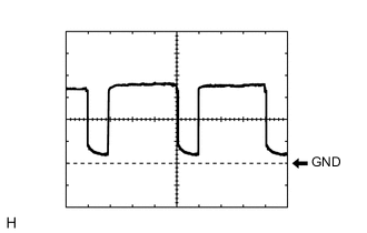
Waveform 1:
Item Content Terminal No. G37-22 (BLW) - Body ground
G37-23 (RCRL) - Body ground
Tool Setting 2 V/DIV., 500 μs/DIV. Vehicle Condition
-
Ignition switch ON
-
Blower switch: LO
-
-
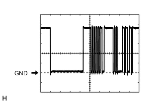
Waveform 2:
Item Content Terminal No. h3-3 (BUS) - h3-2 (BUSG) Tool Setting 2 V/DIV., 2 ms/DIV. Vehicle Condition Ignition switch ON
-
-
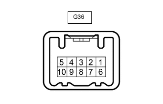
AIR CONDITIONING CONTROL ASSEMBLY
-
Disconnect the G36 air conditioning control assembly connector.
-
Measure the resistance and voltage according to the value(s) in the table below.
Terminal No.
(Symbol)
Wiring Color Terminal Description Condition Specified Condition G36-2 (IG+) - Body ground L - Body ground Power source (IG) Ignition switch ON 11 to 14 V Ignition switch off Below 1 V G36-4 (GND) - Body ground W-B - Body ground Ground for air conditioning control assembly Always Below 1 Ω -
Reconnect the G36 air conditioning control assembly connector.
-
Measure the waveform according to the value(s) in the table below.
Terminal No.
(Symbol)
Wiring Color Terminal Description Condition Specified Condition G36-3 (LIN1) - Body ground R - Body ground LIN communication signal Ignition switch ON Pulse generation
-
-
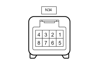
INTEGRATION CONTROL AND PANEL ASSEMBLY
-
Disconnect the N34 integration control and panel assembly connector.
-
Measure the resistance and voltage according to the value(s) in the table below.
Terminal No.
(Symbol)
Wiring Color Terminal Description Condition Specified Condition N34-8 (IG+) - Body ground G - Body ground Power source (IG) Ignition switch ON 11 to 14 V Ignition switch off Below 1 V N34-5 (GND) - Body ground W-B - Body ground Ground for air conditioning control assembly Always Below 1 Ω -
Reconnect the N34 integration control and panel assembly connector.
-
Measure the waveform according to the value(s) in the table below.
Terminal No.
(Symbol)
Wiring Color Terminal Description Condition Specified Condition N34-6 (LIN1) - Body ground R - Body ground LIN communication signal Ignition switch ON Pulse generation
-
-
ECM
-
for 1GR-FE: Click here
-
for 1GD-FTV: Click here
-
for 1GD-FTV (w/DPF): Click here
-
for 1GD-FTV (w/ EGR System): Click here
-
for 1GD-FTV (w/ EGR Cooler): Click here
-
for 2GD-FTV: Click here
-
for 2GD-FTV (w/o EGR Cooler): Click here
-
for 2TR-FE: Click here
-