REAR NO. 2 SEAT ASSEMBLY REMOVAL
CAUTION / NOTICE / HINT
CAUTION:
-
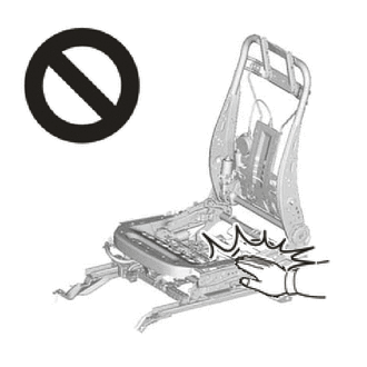
Wear protective gloves. Sharp areas on the parts may injure your hands.
-
There is risk of injury.
-
Replace any other damaged parts as necessary.
Tech Tips
-
Use the same procedure for the RH and LH sides.
-
The procedure listed below is for the RH side.
PROCEDURE
-
REMOVE NO.2 SEAT HEADREST ASSEMBLY
-
Remove the No. 2 seat headrest assembly.
-
-
REMOVE REAR SEAT CUSHION UNDER COVER RH
-
Set the rear No. 2 seat assembly RH to the upright position.
-
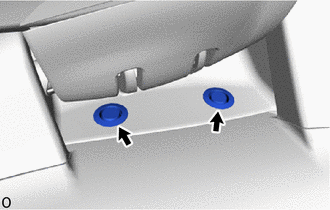
Remove the 2 hole plugs.
-
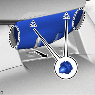

Place Hand Here 
Remove in this Direction Place your hand at the position shown in the illustration and pull in the remove direction to detach the clip to remove the rear seat cushion under cover RH.
-
-
REMOVE SEAT ADJUSTER COVER CAP RH
-
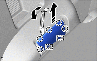
Remove in this Direction Lock the rear No. 2 seat leg assembly RH to the floor striker and set the rear No. 2 seat to the upright position.
-
Using moulding remover A, lift in the direction indicated by the arrow shown in the illustration and pull in the removal direction to detach the claw and guide to remove seat adjuster cover cap RH.
-
-
REMOVE REAR NO. 2 SEAT ASSEMBLY RH
-
Install stopper bolt in that order, as shown in the illustration.
- Torque:
- 17 N*m { 173 kgf*cm, 13 ft.*lbf }
Note
For the stopper bolts, use replacement parts (72702-0K220) or bolts which conform to the appropriate measurements (M8 x 1.25)
Tech Tips
The dimensions of each part of the stopper bolt are shown in the following chart.
Part Dimension A 14 mm B 24 mm or less C 9 mm or less D 45.4 mm E 33.1 mm F 1 mm or less (all around) G 2.5 mm or less H M8 x 1.25 I 10.5 mm or more J 4 mm or more K 22 mm or more L 12 mm 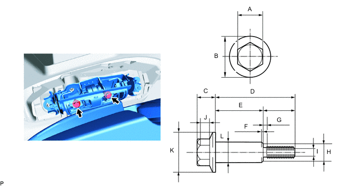
-
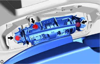
Remove the 3 bolts.
-
Remove the 2 pop-up prevention bolts and rear No. 2 seat assembly RH.
Note
-
Protect the front seat legs.
-
Do not damage the rear No. 2 seat assembly RH, body exterior or interior parts.
-
-