METER / GAUGE SYSTEM Tachometer Malfunction
DESCRIPTION
In this circuit, the combination meter assembly receives engine speed signals from the ECM via the CAN communication system. The combination meter assembly displays the engine speed calculated based on the data received from the ECM.
WIRING DIAGRAM
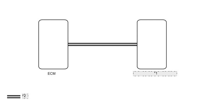
| *1 | Combination Meter Assembly |
| *2 | CAN Communication Line |
CAUTION / NOTICE / HINT
Note
-
When replacing the combination meter assembly, make sure to replace it with a new one.
-
Depending on the parts that are replaced during vehicle inspection or maintenance, performing initialization, registration or calibration may be needed.
PROCEDURE
-
CHECK FOR DTC (CAN COMMUNICATION SYSTEM)
-
Check for DTCs.
OK No DTCs are output. Result Result OK NG
NG 
GO TO CAN COMMUNICATION SYSTEM Click here
OK 
-
-
CHECK FOR DTC (ECD SYSTEM)
-
Check for DTCs.
Powertrain > Engine and ECT > Trouble CodesOK No DTCs are output. Result Result OK NG
NG
GO TO ECD SYSTEM Click here
OK
-
-
PERFORM ACTIVE TEST USING GTS (TACHOMETER OPERATION)
-
Using the GTS, perform the Active Test.
Body Electrical > Combination Meter > Active TestTester Display Measurement Item Control Range Diagnostic Note TachoMeter Operation Tachometer OFF, 0, 1000, 2000, 3000, 4000 or 5000 (rpm) -
Body Electrical > Combination Meter > Active TestTester Display TachoMeter Operation OK Tachometer indication is normal. Result Proceed to OK NG
NG
REPLACE COMBINATION METER ASSEMBLY Click here
OK
-
-
READ VALUE USING GTS (ENGINE SPEED, ENGINE RPM)
-
Using the GTS, read the Data List.
Powertrain > Engine and ECT > Data ListTester Display Measurement Item Normal Condition Reference Value Diagnostic Note Engine Speed Engine speed Min.: 0 rpm, Max.: 16383 rpm Actual engine speed -
Body Electrical > Combination Meter > Data ListTester Display Measurement Item Range Normal Condition Diagnostic Note Engine Rpm Engine speed Min.: 0 rpm, Max.: 12750 rpm Actual engine speed -
Powertrain > Engine and ECT > Data ListTester Display Engine Speed
Body Electrical > Combination Meter > Data ListTester Display Engine Rpm Tech Tips
-
When the Data List values of the ECUs match, an internal malfunction of the ECM is suspected.
-
When the Data List values of the ECUs do not match, a signal output error of the ECM or an internal malfunction of the combination meter assembly is suspected.
OK The Data List values of the ECUs do not match. Result Result OK NG -
NG
REPLACE ECM Click here
OK
-
-
CHECK COMBINATION METER ASSEMBLY
-
Replace the combination meter assembly with a new one.
-
Check that the operation of the tachometer returns to normal.
OK The operation of the tachometer returns to normal. Result Result OK NG
OK
END (COMBINATION METER ASSEMBLY IS DEFECTIVE)
NG
REPLACE ECM Click here
-