METER / GAUGE SYSTEM, Diagnostic DTC:B150A
| DTC Code | DTC Name |
|---|---|
| B150A | Lost Communication with HMI-LAN |
DESCRIPTION
The combination meter assembly receives a text data signal from the navigation receiver assembly*1 or radio and display receiver assembly*2 via local bus communication.
Based on this signal, audio and visual system or navigation system information is displayed on the multi-information display.
This DTC is stored when the combination meter assembly cannot receive the signal.
| DTC No. | Detection Item | DTC Detection Condition | Trouble Area |
|---|---|---|---|
| B150A | Lost Communication with HMI-LAN | After the combination meter assembly receives a registration information signal, which is sent by the navigation receiver assembly*1 or radio and display receiver assembly*2 when the ignition switch is ACC, 1 or more times, the combination meter assembly cannot receive the signal for 30 seconds or more. |
|
-
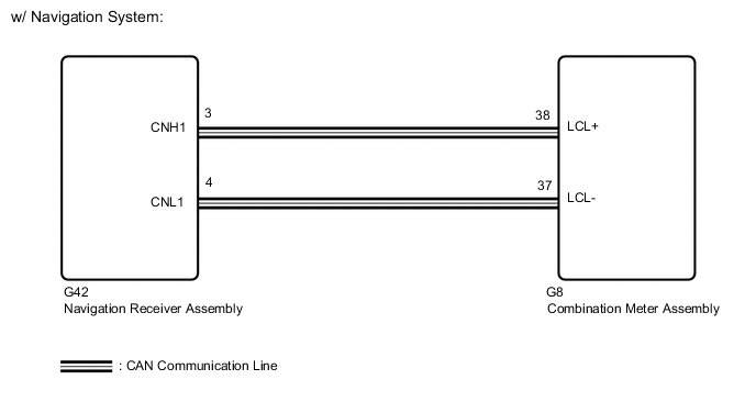
*1: w/ Navigation System
-
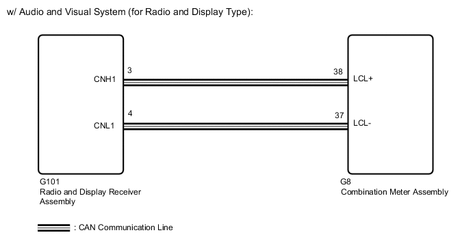
*2: w/ Audio and Visual System (for Radio and Display Type)
WIRING DIAGRAM
CAUTION / NOTICE / HINT
Note
When replacing the combination meter assembly, make sure to replace it with a new one.
PROCEDURE
-
CHECK VEHICLE
-
Check vehicle.
Result Result Proceed to w/ Navigation System A w/ Audio and Visual System (for Radio and Display Type) B
B 
CHECK FOR DTC (AUDIO AND VISUAL SYSTEM) Click here
A 
-
-
CHECK FOR DTC (NAVIGATION SYSTEM)
-
Check for DTCs.
Body Electrical > Navigation System > Trouble CodesOK No DTCs are output. Result Proceed to OK NG
NG 
GO TO NAVIGATION SYSTEM Click here
OK
-
-
CHECK HARNESS AND CONNECTOR (COMBINATION METER ASSEMBLY - NAVIGATION RECEIVER ASSEMBLY)
-
Disconnect the G8 combination meter assembly connector.
-
Disconnect the G42 navigation receiver assembly connector.
-
Measure the resistance according to the value(s) in the table below.
Standard Resistance Tester Connection Condition Specified Condition G8-38 (LCL+) - G42-3 (CNH1) Always Below 1 Ω G8-37 (LCL-) - G42-4 (CNL1) Always Below 1 Ω G8-38 (LCL+) or G42-3 (CNH1) - Body ground Always 10 kΩ or higher G8-37 (LCL-) or G42-4 (CNL1) - Body ground Always 10 kΩ or higher Result Proceed to OK NG
NG
REPAIR OR REPLACE HARNESS OR CONNECTOR
OK
-
-
CHECK COMBINATION METER ASSEMBLY
-
Replace the combination meter assembly with a new one.
-
Turn the ignition switch to ON and wait 30 seconds.
Note
A maximum of 30 seconds is required to send/receive the registration information between the combination meter assembly and multi-media module receiver assembly.
-
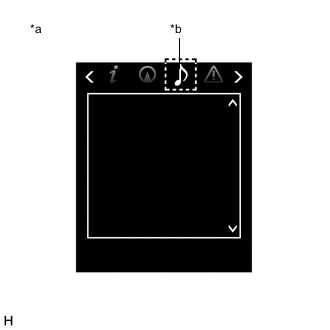
*a Multi-information Display *b Audio Tab Operate the steering pad switch assembly and check that the audio tab illuminates.
-
Check for DTCs.
Body Electrical > Combination Meter > Trouble CodesOK The audio tab illuminates and DTC B150A is not output. Result Proceed to OK NG
OK
END (COMBINATION METER ASSEMBLY IS DEFECTIVE)
NG
REPLACE NAVIGATION RECEIVER ASSEMBLY Click here
-
-
CHECK FOR DTC (AUDIO AND VISUAL SYSTEM)
-
Check for DTCs.
Body Electrical > Navigation System > Trouble CodesOK No DTCs are output. Result Proceed to OK NG
NG
GO TO AUDIO AND VISUAL SYSTEM Click here
OK
-
-
CHECK HARNESS AND CONNECTOR (COMBINATION METER ASSEMBLY - RADIO AND DISPLAY RECEIVER ASSEMBLY)
-
Disconnect the G8 combination meter assembly connector.
-
Disconnect the G101 radio and display receiver assembly connector.
-
Measure the resistance according to the value(s) in the table below.
Standard Resistance Tester Connection Condition Specified Condition G8-38 (LCL+) - G101-3 (CNH1) Always Below 1 Ω G8-37 (LCL-) - G101-4 (CNL1) Always Below 1 Ω G8-38 (LCL+) or G101-3 (CNH1) - Body ground Always 10 kΩ or higher G8-37 (LCL-) or G101-4 (CNL1) - Body ground Always 10 kΩ or higher Result Proceed to OK NG
NG
REPAIR OR REPLACE HARNESS OR CONNECTOR
OK
-
-
CHECK COMBINATION METER ASSEMBLY
-
Replace the combination meter assembly with a new one.
-
Turn the ignition switch to ON and wait 30 seconds.
Note
A maximum of 30 seconds is required to send/receive the registration information between the combination meter assembly and multi-media module receiver assembly.
-
*a Multi-information Display *b Audio Tab Operate the steering pad switch assembly and check that the audio tab illuminates.
-
Check for DTCs.
Body Electrical > Combination Meter > Trouble CodesOK The audio tab illuminates and DTC B150A is not output. Result Proceed to OK NG
OK
END (COMBINATION METER ASSEMBLY IS DEFECTIVE)
NG
REPLACE RADIO AND DISPLAY RECEIVER ASSEMBLY Click here
-